Toyota Sienna 2010-2026 Owners Manual: Unlocking and locking the doors from the outside
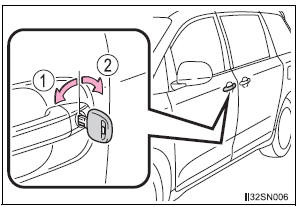
Entry function (vehicles with a smart key system)
Carry the electronic key to enable this function.
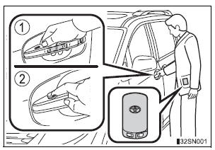
- Grip the driver’s door handle
to unlock the door. Grip the
passenger’s door handle to
unlock all the doors.*
Make sure to touch the sensor
on the back of the handle.
The doors cannot be unlocked for 3 seconds after the doors are locked.
*: The door unlock settings can be changed.
- Touch the lock sensor (the indentation on the upper part of the
door handle) to lock all the doors.
Check that the door is securely locked.
Wireless remote control
- Vehicles without a smart key system (type A)
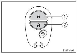
- Locks all doors
Check that the door is securely locked. - Unlocks all doors
Pressing the button unlocks the driver’s side doors. Pressing the button again within 3 seconds unlocks the other doors.
- Vehicles without a smart key system (type B)
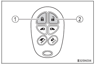
- Locks all doors
Check that the door is securely locked. - Unlocks all doors
Pressing the button unlocks the driver’s side doors. Pressing the button again within 3 seconds unlocks the other doors.
- Vehicles with a smart key system
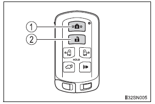
- Locks all doors
Check that the door is securely locked. - Unlocks all doors
Pressing the button unlocks the driver’s side doors. Pressing the button again within 3 seconds unlocks the other doors.
Key
- Vehicles without a smart key system
- Locks all the doors
- Unlocks all the doors
Turning the key unlocks the driver’s side doors. Turning the key again within 3 seconds unlocks the other doors.
- Vehicles with a smart key system
The doors can also be locked and unlocked with the mechanical key.
Operation signals
A buzzer sounds and the emergency flashers flash to indicate that the doors have been locked/unlocked. (Locked: Once; Unlocked: Twice)
Security feature
If a door is not opened within approximately 60 seconds after the vehicle is unlocked, the security feature automatically locks the vehicle again.
When the door cannot be locked by the lock sensor on the upper part of the front door handle
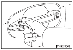
Touch both lock sensors on the upper and lower part of the front door handle simultaneously.
Door lock buzzer
If an attempt to lock the doors (except for power sliding doors or power back door) is made when a door is not fully closed, a buzzer sounds continuously.
Fully close the door to stop the buzzer, and lock the vehicle once more.
Alarm (if equipped)
Using the wireless remote control to lock the doors will set the alarm system.
If the smart key system or the wireless remote control does not operate properly
Vehicles with a smart key system: Use the mechanical key to lock and unlock the doors. Replace the key battery with a new one if it is depleted
 Front doors
...
 Unlocking and locking the doors from the inside
Door lock switch
Locks all the doors
Unlocks all the doors
Inside lock button
Locks the door
Unlocks the door
The front doors can be opened
by pulling the inside handle
eve ...
Other materials:
System Too
DESCRIPTION
The fuel trim is related to the feedback compensation value, not to the basic
injection time. The fuel trim
consists of both the short-term and long-term fuel trims.
The short-term fuel trim is fuel compensation that is used to constantly
maintain the air-fuel ratio at
stoich ...
ECM Communication Stop Mode
DESCRIPTION
Detection Item
Symptom
Trouble Area
ECM Communication Stop
Mode
"Engine" is not displayed on the "Communication
Bus Check" screen of the intelligent tester
Applies to "ECM Communication Stop Mode" in ...
Installation
1. INSTALL REAR NO. 1 SEAT ASSEMBLY CENTER
Place the seat in the cabin.
NOTICE:
Be careful not to damage the body.
Install the rear seat.
Install the seat belt anchor plate with the bolt.
Torque: 42 N*m (428 kgf*cm, 31 ft.*lbf)
Install the headrest.
...
