Toyota Sienna Service Manual: Front Occupant Classification Sensor LH Circuit Malfunction
DTC B1780 Front Occupant Classification Sensor LH Circuit Malfunction
DESCRIPTION
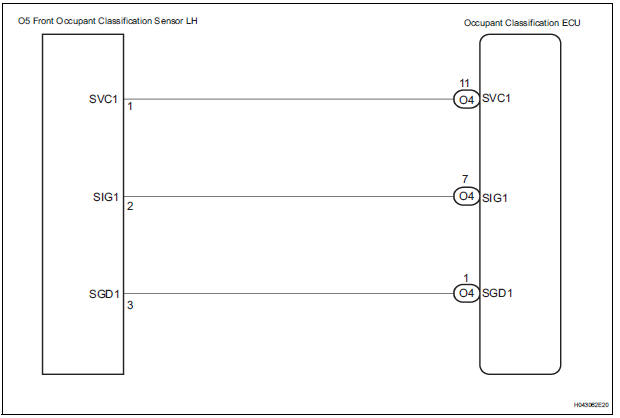
The front occupant classification sensor LH circuit consists of the occupant classification ECU and the front occupant classification sensor LH.
DTC B1780 is recorded when a malfunction is detected in the front occupant classification sensor LH circuit.
|
DTC No. |
DTC Detecting Condition |
Trouble Area |
|
B1780 |
|
|
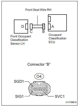
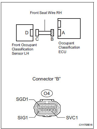
WIRING DIAGRAM
INSPECTION PROCEDURE
HINT:
- If troubleshooting (wire harness inspection) is difficult to perform, remove the front passenger seat installation bolts to see the under surface of the seat cushion.
- In the above case, hold the seat so that it does not fall down. Holding the seat for a long period of time may cause a problem, such as seat rail deformation. Hold the seat only as necessary.
1 CHECK DTC
- Turn the ignition switch to the ON position.
- Clear the DTCs stored in the memory.
HINT: First clear DTCs stored in the occupant classification ECU and then in the center airbag sensor assembly.
- Turn the ignition switch to the LOCK position.
- Turn the ignition switch to the ON position.
- Check the DTCs (35).
OK: DTC B1780 is not output. HINT: Codes other than DTC B1780 may be output at this time, but they are not related to this check.
 USE SIMULATION METHOD TO CHECK

2 CHECK CONNECTION OF CONNECTORS
- Turn the ignition switch to the LOCK position.
- Disconnect the negative (-) terminal cable from the battery, and wait for at least 90 seconds.
- Check that the connectors are properly connected to the occupant classification ECU and the front occupant classification sensor LH.
OK: The connectors are properly connected
 CONNECT CONNECTOR, THEN GO TO
STEP
1
CONNECT CONNECTOR, THEN GO TO
STEP
1

3 CHECK FRONT SEAT WIRE RH (SHORT TO B+)
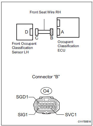
- Disconnect the connectors from the occupant classification ECU and the front occupant classification sensor LH.
- Connect the negative (-) terminal cable to the battery.
- Turn the ignition switch to the ON position.
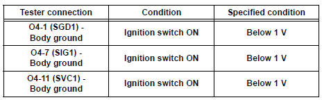
- Measure the voltage according to the value(s) in the table below.
Standard voltage
 REPAIR OR REPLACE FRONT SEAT
WIRE
RH
REPAIR OR REPLACE FRONT SEAT
WIRE
RH

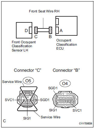
4 CHECK FRONT SEAT WIRE RH (OPEN)
- Turn the ignition switch to the LOCK position.
- Disconnect the negative (-) terminal cable from the battery, and wait for at least 90 seconds.
- Using a service wire, connect O5-1 (SVC1) and O5-3
(SGD1), and connect O5-2 (SIG1) and O5-3 (SGD1) of
connector "C".
NOTICE: Do not forcibly insert a service wire into the terminals of the connector when connecting.
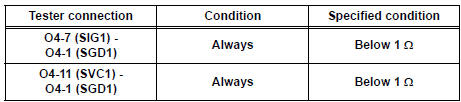
- Measure the resistance according to the value(s) in the table below.
Standard resistance
 REPAIR OR REPLACE FRONT SEAT
WIRE
RH
REPAIR OR REPLACE FRONT SEAT
WIRE
RH

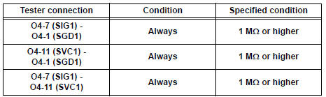
5 CHECK FRONT SEAT WIRE RH (SHORT)
- Disconnect the service wire from connector "C".
- Measure the resistance according to the value(s) in the table below.
Standard resistance
 REPAIR OR REPLACE FRONT SEAT
WIRE
RH
REPAIR OR REPLACE FRONT SEAT
WIRE
RH

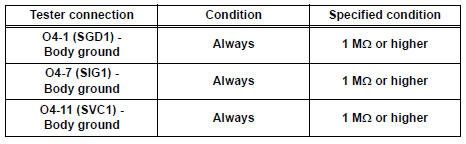
6 CHECK FRONT SEAT WIRE RH (SHORT TO GROUND)
- Measure the resistance according to the value(s) in the table below.
Standard resistance
 REPAIR OR REPLACE FRONT SEAT
WIRE
RH
REPAIR OR REPLACE FRONT SEAT
WIRE
RH

7 CHECK DTC
- Connect the connectors to the occupant classification ECU and the front occupant classification sensor LH.
- Connect the negative (-) terminal cable to the battery.
- Turn the ignition switch to the ON position.
- Clear the DTCs stored in the memory.
HINT: First clear DTCs stored in the occupant classification ECU and then in the center airbag sensor assembly.
- Turn the ignition switch to the LOCK position.
- Turn the ignition switch to the ON position.
- Check the DTCs (35).
OK: DTC B1780 is not output. HINT: Codes other than DTC B1780 may be output at this time, but they are not related to this check.
 USE SIMULATION METHOD TO CHECK

8 REPLACE OCCUPANT CLASSIFICATION ECU
- Turn the ignition switch to the LOCK position.
- Disconnect the negative (-) terminal cable from the battery, and wait for at least 90 seconds.
- Replace the occupant classification ECU.
HINT: Perform the inspection using parts from a normal vehicle if possible.

9 PERFORM ZERO POINT CALIBRATION
- Connect the negative (-) terminal cable to the battery.
- Connect the intelligent tester to the DLC3.
- Turn the ignition switch to the ON position.
- Using the intelligent tester, perform "Zero point calibration" (28).
OK: "COMPLETED" is displayed.
 Go to step 12

10 PERFORM SENSITIVITY CHECK
- Using the intelligent tester, perform "Sensitivity check" (28).
Standard value: 27 to 33 kg (59.52 to 72.75 lb)
 Go to step 12

11 CHECK DTC
- Turn the ignition switch to the ON position.
- Clear the DTCs stored in the memory.
HINT: First clear DTCs stored in the occupant classification ECU and then in the center airbag sensor assembly.
- Turn the ignition switch to the LOCK position.
- Turn the ignition switch to the ON position.
- Check the DTCs (35).
OK: DTC B1780 is not output. HINT: Codes other than DTC B1780 may be output at this time, but they are not related to this check.
 END
END

12 REPLACE FRONT SEAT ASSEMBLY RH
- Turn the ignition switch to the LOCK position.
- Disconnect the negative (-) terminal cable from the battery, and wait for at least 90 seconds.
- Replace the front seat assembly RH.

13 PERFORM ZERO POINT CALIBRATION
- Connect the negative (-) terminal cable to the battery.
- Connect the intelligent tester to the DLC3.
- Turn the ignition switch to the ON position.
- Using the intelligent tester, perform "Zero point calibration" (28).
OK: "COMPLETED" is displayed.

14 PERFORM SENSITIVITY CHECK
- Using the intelligent tester, perform "Sensitivity check" (28).
Standard value: 27 to 33 kg (59.52 to 72.75 lb)

END
 Passenger Side Buckle Switch Circuit Malfunction
DTC B1771 Passenger Side Buckle Switch Circuit Malfunction
DESCRIPTION
The passenger side buckle switch circuit consists of the occupant
classification ECU and the front seat
inner belt assembly ...
 Front Occupant Classification Sensor RH Circuit
Malfunction
Front Occupant Classification Sensor RH Circuit
Malfunction
DTC B1781 Front Occupant Classification Sensor RH Circuit
Malfunction
DESCRIPTION
The front occupant classification sensor RH circuit consists of the occupant
classification ECU and the
front oc ...
Other materials:
Throttle Actuator Control System
DTC P2111 Throttle Actuator Control System - Stuck Open
DTC P2112 Throttle Actuator Control System - Stuck
Closed
DESCRIPTION
The throttle actuator is operated by the ECM, and opens and closes the
throttle valve using the gears.
The opening angle of the throttle valve is detected by the Thr ...
Diagnostic trouble code chart
COMMUNICATION DIAGNOSIS:
SW:
SW WITH NAME:
SW CONVERTING:
COMMAND SW:
FRONT MONITOR:
DVD PLAYER:
TELEPHONE:
NAVI:
IN-DASH CD CHANGER:
GPS:
CAMERA UNIT:
...
Front No. 2 speaker
COMPONENTS
ON-VEHICLE INSPECTION
1. INSPECT FRONT NO.2 SPEAKER
HINT:
Remove interior parts so that the front No.2 speaker can
be seen.
Check the speaker installation.
OK:
The speaker is securely installed.
If the result is not as specified, reinstall the front
No.2 speak ...
