Toyota Sienna Service Manual: ABS Warning Light does not Come ON
WIRING DIAGRAM
Refer to ABS Warning Light Remains ON (See page BC-141).
INSPECTION PROCEDURE
1 CHECK ABS WARNING LIGHT
(a) Disconnect the skid control ECU connector.
(b) Turn the ignition switch to the ON position.
(c) Check that the ABS warning light comes on.
OK: ABS warning light comes on.
HINT: If troubleshooting has been carried out according to the PROBLEM SYMPTOMS TABLE, refer back to the table and proceed to the next step (See page BC-79).

REPLACE BRAKE ACTUATOR ASSEMBLY
2 CHECK HARNESS AND CONNECTOR (SKID CONTROL ECU - COMBINATION METER)
(a) Turn the ignition switch off.
(b) Disconnect the combination meter connector.
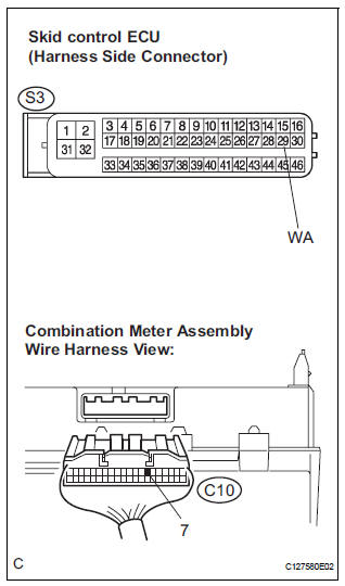
(c) Measure the resistance according to the value(s) in the table below.
Standard resistance 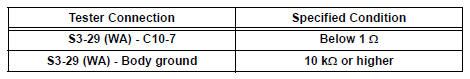

3 INSPECT COMBINATION METER ASSEMBLY
(a) Check the combination meter (See page ME-4).
HINT: If troubleshooting has been carried out according to the PROBLEM SYMPTOMS TABLE, refer back to the table and proceed to the next step (See page BC-79).

END
 ABS Warning Light Remains ON
DESCRIPTION
If any of the following is detected, the ABS warning light remains on.
The skid control ECU connectors are disconnected from the skid control
ECU.
There is a malfunction in the s ...
 VSC Warning Light Remains ON
DESCRIPTION
The skid control ECU is connected to the combination meter via CAN and
multiplex communications.
If the skid control ECU stores DTCs to shut down TRAC and VSC operation, the VSC
wa ...
Other materials:
Removal
1. Remove front wheel
2. Remove front wiper arm head cap
Hint:
(see page ww-3)
3. Remove fr wiper arm rh
HINT:
(See page WW-3)
4. Remove fr wiper arm lh
HINT:
(See page WW-3)
5. Remove cowl top ventilator louver subassembly
Hint:
(see page ww-3)
6. Remove windshield wiper motor & li ...
Installation
1. INSTALL BLOWER ASSEMBLY
(a) Install the blower assembly.
(b) Install the bolt, the 2 screws and the nut.
Torque: Bolt A
9.8 N*m (100 kgf*cm, 87 in.*lbf)
(c) Install the 2 clamps and 2 nuts and wire harness.
2. INSTALL INSTRUMENT PANEL SUB-ASSEMBLY WITH PASSENGER AIRBAG ASSEMBLY
H ...
Terminals of ECM
1. SFI SYSTEM
HINT:
The standard normal voltage between each pair of the
ECM terminals is shown in the table below. The
appropriate conditions for checking each pair of the
terminals are also indicated.
The check results should be compared with the standard
normal voltage for that pair of ...
