Toyota Sienna Service Manual: VSC Warning Light Remains ON
DESCRIPTION
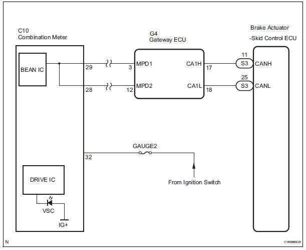
The skid control ECU is connected to the combination meter via CAN and multiplex communications.
If the skid control ECU stores DTCs to shut down TRAC and VSC operation, the VSC warning light comes on in the combination meter.
WIRING DIAGRAM
INSPECTION PROCEDURE
NOTICE: When replacing the brake actuator assembly, perform zero point calibration (See page BC-70).
1 CHECK CAN COMMUNICATION SYSTEM
(a) Check if the CAN communication system DTC is output (See page CA-17).
Result 

2 CHECK MULTIPLEX COMMUNICATION SYSTEM
(a) Check if the multiplex communication system DTC is output (See page MP-14).
Result 

3 CHECK IF SKID CONTROL ECU CONNECTOR IS SECURELY CONNECTED
(a) Check if the skid control ECU connector is securely connected.
OK: The connector is securely connected.

4 CHECK BATTERY
(a) Check the battery voltage.
Standard voltage: 11 to 14 V

5 INSPECT COMBINATION METER ASSEMBLY
(a) Check the combination meter (See page ME-4).
OK: The combination meter is normal.
HINT: If troubleshooting has been carried out according to the Problem Symptoms Table, refer back to the table and proceed to the next step before replacing the part (See page BC-79).

REPLACE BRAKE ACTUATOR ASSEMBLY
 ABS Warning Light does not Come ON
WIRING DIAGRAM
Refer to ABS Warning Light Remains ON (See page BC-141).
INSPECTION PROCEDURE
1 CHECK ABS WARNING LIGHT
(a) Disconnect the skid control ECU connector.
(b) Turn the ignition switc ...
 VSC Warning Light does not Come ON
DESCRIPTION
The skid control ECU is connected to the combination meter via CAN and
multiplex communications.
If the skid control ECU stores DTCs to shut down TRAC and VSC operation, the VSC
wa ...
Other materials:
Installation
1. INSTALL SEAT MEMORY SWITCH
2. INSTALL FRONT DOOR TRIM BOARD SUBASSEMBLY
LH
3. INSTALL POWER WINDOW REGULATOR MASTER
SWITCH ASSEMBLY
4. INSTALL FRONT DOOR INSIDE HANDLE BEZEL
PLUG LH
5. INSTALL FRONT DOOR LOWER FRAME BRACKET GARNISH LH
Engage the 4 claws to install the seat me ...
Short in Side Squib RH Circuit
DTC B0110/43 Short in Side Squib RH Circuit
DESCRIPTION
The side squib RH circuit consists of the center airbag sensor assembly and
the front seat side airbag
assembly RH.
The circuit instructs the SRS to deploy when deployment conditions are met.
DTC B0110/43 is recorded when a short cir ...
Removal
1. REMOVE WINDSHIELD WIPER MOTOR ASSEMBLY
2. REMOVE FRONT OUTER COWL TOP PANEL SUBASSEMBLY
3. DRAIN ENGINE COOLANT
4. REMOVE V-BANK COVER SUB-ASSEMBLY
5. REMOVE NO. 2 AIR CLEANER INLET
6. REMOVE NO. 1 AIR CLEANER INLET
7. REMOVE AIR CLEANER CAP SUB-ASSEMBLY
Disconnect the 3 vacuum hoses.
...
