Toyota Sienna Service Manual: Terminals of ECM
1. SFI SYSTEM
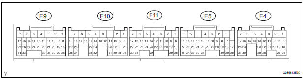
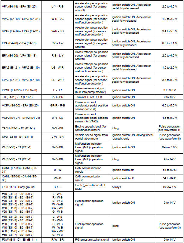
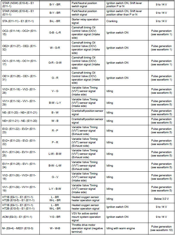
HINT: The standard normal voltage between each pair of the ECM terminals is shown in the table below. The appropriate conditions for checking each pair of the terminals are also indicated.
The check results should be compared with the standard normal voltage for that pair of terminals, listed in the "Specified Condition" column.
The illustration above can be used as a reference to identify the ECM terminal locations.
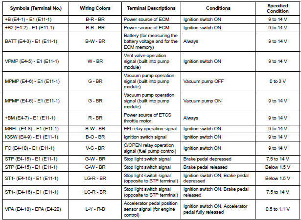
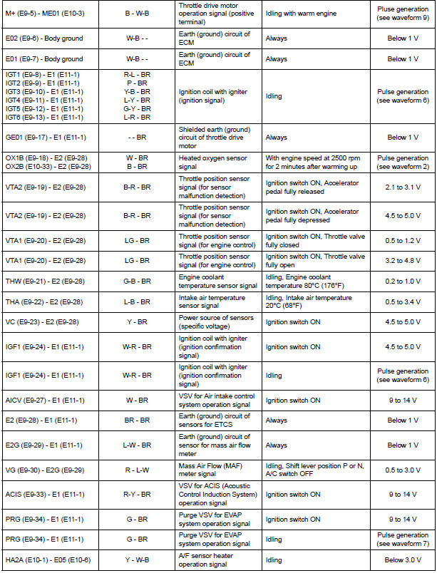
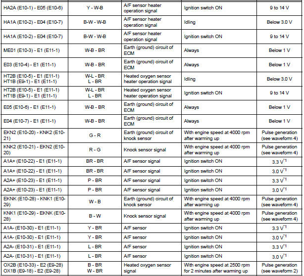
*1: The ECM terminal voltage is constant regardless of the output voltage from the sensor.
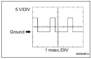
- WAVEFORM 1
- Camshaft Timing Oil Control Valve (OCV) operation signal
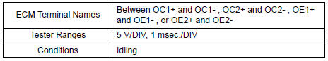
HINT: The wavelength becomes shorter as the engine rpm increases.
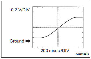
- WAVEFORM 2
- Heated oxygen sensor signal
HINT: In the DATA LIST, item O2S B1S2 shows the ECM input values from the heated oxygen sensor.
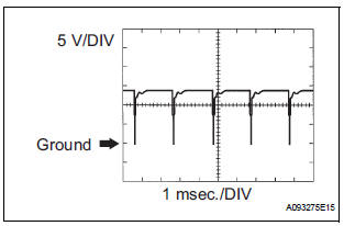
- WAVEFORM 3
- Fuel injector operation signal
HINT: The wavelength becomes shorter as the engine rpm increases.
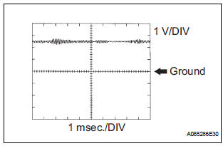
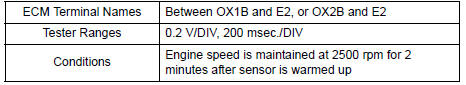
- WAVEFORM 4
- Knock sensor signal
HINT:
- The wavelength becomes shorter as the engine rpm increases.
- The waveforms and amplitudes displayed differ slightly depending on the vehicle.
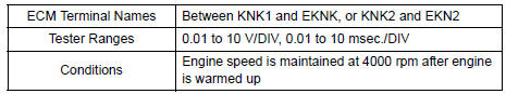
- WAVEFORM 5
- Variable Valve Timing (VVT) sensor signal (1)
- Crankshaft position sensor signal (2)
HINT: The wavelength becomes shorter as the engine rpm increases.
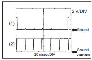
- WAVEFORM 6
- Igniter IGT signal (from ECM to igniter) (1)
- Igniter IGF signal (from igniter to ECM) (2)
HINT: The wavelength becomes shorter as the engine rpm increases.
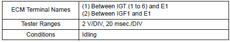
- WAVEFORM 7
- Purge VSV for EVAP system operation signal
HINT: If the waveform is not similar to that shown in the illustration, check the waveform again after idling for 10 minutes or more.
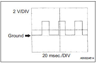
- WAVEFORM 8
- Vehicle speed signal
HINT:
- The wavelength becomes shorter as the vehicle speed increases.
- Depending on the vehicle, the output waveform voltage may rise to 12 V if influenced by optionally installed systems.
- WAVEFORM 9
- Throttle drive motor operation signal (positive terminal)
HINT: The duty ratio varies depending on the throttle actuator operation.
- WAVEFORM 10
- Throttle drive motor operation signal (negative terminal)
HINT: The duty ratio varies depending on the throttle actuator operation.
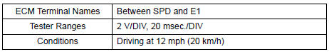
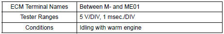
- WAVEFORM 11
- Engine speed signal
HINT: The wavelength becomes shorter as the engine rpm increases.
 Problem symptoms table
HINT:
When a malfunction is not confirmed by a DTC (Diagnostic
Trouble Code) check and the cause of problem cannot be
identified through a basic inspection, troubleshoot according
to the priority ...
 Diagnosis system
1. DESCRIPTION
When troubleshooting OBD II (On-Board
Diagnostics) vehicles, an intelligent tester
(complying with SAE J1987) must be connected to
the DLC3 (Data Link Connector 3) o ...
Other materials:
Replacement
1. DISCHARGE REFRIGERANT FROM
REFRIGERATION SYSTEM
SST 07110-58060 (07117-58080, 07117-58090,
07117-78050, 07117-88060, 07117-88070,
07117-88080)
(a) Turn the A/C switch to ON.
(b) Operating the cooler compressor at the engine rpm
of approx. 1,000 for 5 to 6 minutes, circulate the
refriger ...
Rear Air Mix Damper Control Servo Motor Circuit
DESCRIPTION
The rear air mix control servo motor (water valve servo motor) is controlled
by the A/C amplifier.
The rear air mix control servo motor moves the air mix damper by rotating
(normal, reverse) with electrical
power from the A/C amplifier.
WIRING DIAGRAM
INSPECTION PROCEDURE
...
Registration
1. REGISTRATION TRANSMITTER CODE
HINT:
The garage door opener is built in the dome lamp
assembly No.1. When transmitter codes for garage door,
gate, entry gate, door lock, home lighting system or
security system are registered with the garage door
opener, be sure to register them again wheneve ...
