Toyota Sienna Service Manual: Audio terminal
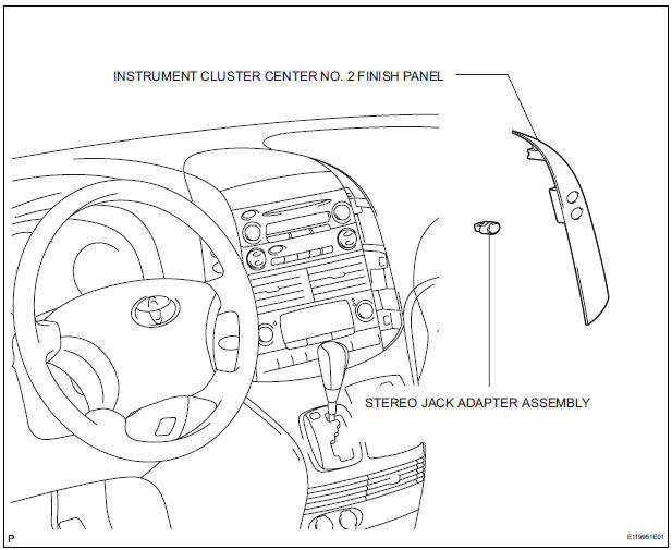
COMPONENTS
REMOVAL
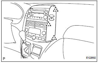
1. REMOVE INSTRUMENT CLUSTER CENTER NO. 2 FINISH PANEL
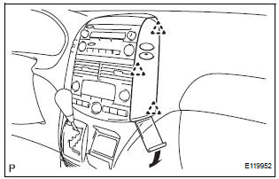
- Using a moulding remover, disengage the 3 clips.
- Disconnect the connector and remove the instrument cluster center No. 2 finish panel.
2. REMOVE STEREO JACK ADAPTER ASSEMBLY
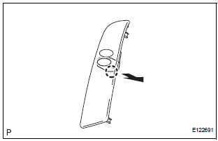
- Disengage the claw and remove the stereo jack adapter assembly.
INSTALLATION
1. INSTALL STEREO JACK ADAPTER ASSEMBLY
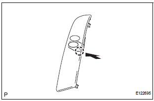
- Engage the claw to install the stereo jack adapter assembly.
2. INSTALL INSTRUMENT CLUSTER CENTER NO. 2 FINISH PANEL
- Connect the connector
- Engage the 3 clips to install the instrument cluster center No. 2 finish panel.
 Video terminal
COMPONENTS
REMOVAL
1. REMOVE REAR DOOR SCUFF PLATE LH
2. REMOVE REAR DOOR WEATHERSTRIP LH
3. REMOVE BACK DOOR WEATHERSTRIP
4. REMOVE BACK DOOR SCUFF PLATE
5. REMOVE QUARTER TRIM FRONT PANE ...
 Steering pad switch
COMPONENTS
...
Other materials:
Pressure Control Solenoid "C" Performance (Shift
Solenoid Valve SL3)
SYSTEM DESCRIPTION
The ECM uses signals from the vehicle speed sensor to detect the actual gear
position (1st, 2nd, 3rd, 4th
or 5th gear).
Then the ECM compares the actual gear with the shift schedule in the ECM memory
to detect mechanical
troubles of the shift solenoid valves and valve bo ...
Diagnosis Circuit
DESCRIPTION
DTC output mode is set by connecting terminals TC and CG of the DLC3.
DTCs are displayed by blinking the SRS warning light.
HINT:
When each warning light stays blinking, a ground short in the
wiring of terminal TC of the DLC3 or an
internal ground short in each ECU is ...
DTC check / clear
1. DTC CHECK (USING SST CHECK WIRE)
Check the DTCs (Present trouble code).
Turn the ignition switch ON, and wait for
approximately 60 seconds.
Using SST, connect terminals TC and CG of the
DLC3.
SST 09843-18040
NOTICE:
Connect the terminals to the correct
positi ...
