Toyota Sienna Service Manual: Checking monitor status
The purpose of the monitor result (mode 06) is to allow access to the results for on-board diagnostic monitoring tests of specific components/systems that are not continuously monitored. Examples are catalyst, evaporative emission (EVAP) and thermostat.
The monitor result allows the OBD II scan tool to display the monitor status, test value, minimum test limit and maximum test limit. These data are displayed after the vehicle has been driven to run the monitor.
When the test value is not between the minimum test limit and maximum test limit, the ECM (PCM) interprets this as a malfunction. When the component is not malfunctioning, if the difference of the test value and test limit is very small, the component will malfunction in the near future.
Perform the following instructions to view the monitor status.
Although the Lexus diagnostic tester is used in the following instructions, it can be checked using a generic OBD II scan tool. Refer to your scan tool operator's manual for specific procedures.
1. PERFORM MONITOR DRIVE PATTERN
The monitor results and test values can be checked with the OBD II scan tool or the intelligent tester. The engine control module (ECM) monitors the emissions-related components such as the thermostat, catalyst converter and evaporative emissions (EVAP), and determines whether they are functioning normally or not. When monitoring is finished, the ECM stores the monitor results and the test values. The monitor result indicates whether the component is functioning normally or not.
The test value is the value that was used to determine the monitor result. If the test value is outside of the test limit (malfunction criterion), the ECM determines the component is malfunctioning. Some emissions-related components have multiple test values to determine monitor result. If one of these test values is outside of the test limit, the ECM determines the component is malfunctioning.
- Connect the intelligent tester to the DLC3.
- Start the engine and turn the tester on.
- Clear the DTCs.
- Run the vehicle in accordance with the applicable drive pattern described in READINESS MONITOR DRIVE PATTERN. DO NOT turn the ignition switch off.
NOTICE: The test results will be lost if the ignition switch is turned off.
2. ACCESS MONITOR RESULT
- Select the following menus on the intelligent tester: DIAGNOSIS, ENHANCED OBDII, MONITOR INFO and MONITOR RESULT. The monitor status appears after the component name.
- INCMP: The component has not been monitored yet.
- PASS: The component is functioning normally.
- FAIL: The component is malfunctioning.
- Confirm that the component is either PASS or FAIL.
- Select the component and press ENTER. The accuracy test value appears if the monitor status is either PASS or FAIL.
HINT: The monitor result might be PASS on rare occasions even if the Malfunction Indicator Lamp (MIL) is illuminated. This indicates that the system was malfunctioning in the previous driving cycle.
This might be caused by an intermittent problem.
3. CHECK COMPONENT STATUS
- Compare the test value with the minimum test limit (MIN LIMIT) and maximum test limit (MAX LIMIT).
- If the test value is between the minimum test limit and maximum test limit, the component is functioning normally. If not, the component is malfunctioning. The test value is usually significantly higher or lower than the test limit. If the test value is on the borderline of the test limit, the component will malfunction in the near future.
HINT: The monitor result might be PASS on rare occasions even if the Malfunction Indicator Lamp (MIL) is illuminated. This indicates that the system was malfunctioning in the previous driving cycle. This might be caused by an intermittent problem.
4. MONITOR RESULT INFORMATION
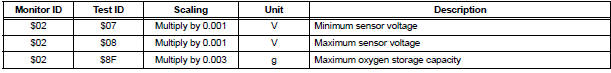
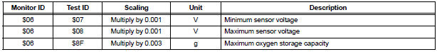
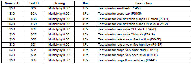
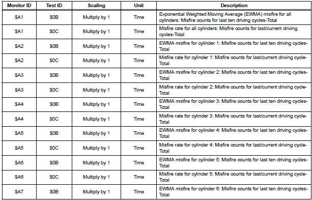
If you use a generic scan tool, multiply the test value by the scaling value listed below.
A/F Sensor Bank 1

HO2S Bank 1 Sensor 2
A/F Sensor Bank 2

HO2S Bank 2 Sensor 2
Catalyst-Bank 1

Catalyst-Bank 2

EVAP
Misfire

Rear Oxygen Sensor Heater

 Registration
NOTICE:
The Vehicle Identification Number (VIN) must be input
into the replacement ECM.
HINT:
The VIN is a 17-digit alphanumeric vehicle identification
number. The intelligent tester is required ...
 Readiness monitor drive
pattern
Readiness monitor drive
pattern
1. PURPOSE OF READINESS TESTS
The On-Board Diagnostic (OBD II) system is
designed to monitor the performance of emissionrelated
components, and indicate any detected
abnormalities with ...
Other materials:
Reassembly
1. INSTALL NO. 1 SEAT CUSHION FRAME SUBASSEMBLY
Install the seat cushion frame with the bolt.
Torque: 20.6 N*m (210 kgf*cm, 15 ft.*lbf)
2. INSTALL RECLINING CONTROL LINK SUBASSEMBLY
Install the reclining control link with the E-ring.
Install the nut.
3. INSTALL RE ...
Removal
1. REMOVE REAR WINDOW SIDE GARNISH
ASSEMBLY
2. REMOVE REAR DOOR WINDOW FRAME SUBASSEMBLY
3. REMOVE SIDE TRIM BOARD COVER REAR
4. REMOVE REAR DOOR TRIM BOARD SUBASSEMBLY
5. REMOVE REAR DOOR GLASS RUN
6. REMOVE SLIDE DOOR WINDOW ASSEMBLY
7. REMOVE REAR DOOR GLASS WEATHERSTRIP
Put pro ...
BluetoothÂź Audio
Listening to BluetoothÂź Audio
The BluetoothÂź audio system enables the user to enjoy music
played on a portable player from the vehicle speakers via wireless
communication.
When a BluetoothÂź device cannot be connected, check the connection
status on the âBluetooth* Audioâ screen. If the ...
