Toyota Sienna Service Manual: Disassembly
1. REMOVE GENERATOR CLUTCH PULLEY
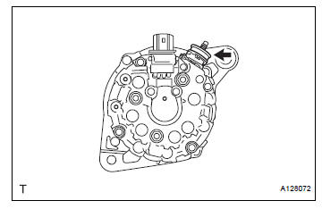
(A) using a screwdriver, remove the generator pulley cap.
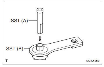
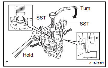
(b) Set SST (A) and (B).
SST 09820-63020
(c) Clamp SST (A) in a vise.
| NOTICE: Be sure to fix the flat surface of SST (A) in a vise. |
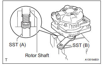
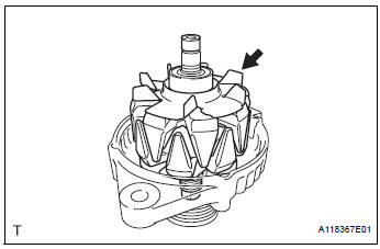
(d) Place the rotor shaft end into SST (A).
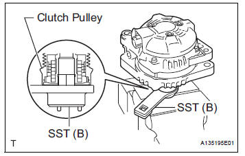
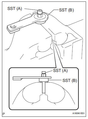
(e) Fit SST (B) to the clutch pulley.
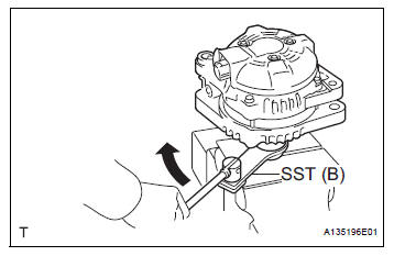
(f) Loosen the pulley by turning SST (B) in the direction shown in the illustration.
| NOTICE: Hold the generator assembly tightly. |
(g) Remove the generator assembly from SST.
(h) Remove the clutch pulley from the rotor shaft.
2. REMOVE GENERATOR REAR END COVER
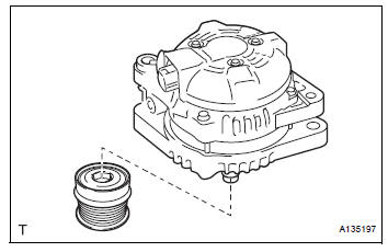
(a) Place the generator assembly on the clutch pulley.
(b) Remove the 3 nuts and generator rear end cover.
3. REMOVE GENERATOR TERMINAL INSULATOR
(a) Remove the terminal insulator from the generator coil.
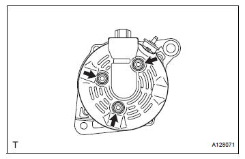
4. REMOVE GENERATOR BRUSH HOLDER ASSEMBLY
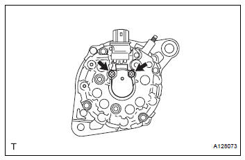
(a) Remove the 2 screws and brush holder from the generator coil.
5. REMOVE GENERATOR COIL ASSEMBLY
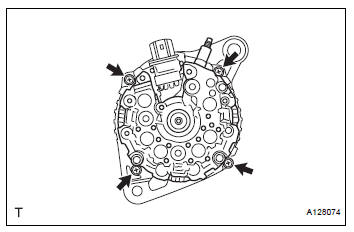
(a) Remove the 4 bolts.
(b) Using SST, remove the generator coil assembly.
SST 09950-40011 (09951-04020, 09952-04010, 09953-04020, 09954-04010, 09955-04071, 09957-04010, 09958-04011)
6. REMOVE GENERATOR ROTOR ASSEMBLY
(a) Remove the generator washer.
(b) Remove the generator rotor assembly.
 Removal
1. Remove v-bank cover sub-assembly (see
page em-28)
2. Remove front wheel rh
3. Remove no. 1 Engine under cover (see page
em-26)
4. Remove front fender apron seal rh (see
page em-26)
5. Drain ...
 Inspection
1. Inspect generator clutch pulley
(a) Hold the center of the pulley, and confirm that the
outer ring turns counterclockwise and does not turn
clockwise.
If the result is not as specified, r ...
Other materials:
Installation
1. INSTALL FOG LIGHT ASSEMBLY
Install the fog light assembly with the 2 claws and 2
pins.
2. INSTALL FRONT BUMPER ASSEMBLY
3. CONNECT CABLE TO NEGATIVE BATTERY
TERMINAL
4. VEHICLE PREPARATION FOR FOG LIGHT AIMING
5. PREPARATION FOR FOG LIGHT AIMING
6. FOG LIGHT AIMING INSPECT ...
No. 1 Clearance Warning Buzzer Circuit
DESCRIPTION
The clearance warning ECU receives the ultrasonic sensor signal to sound the
front warning buzzer.
WIRING DIAGRAM
INSPECTION PROCEDURE
1 INSPECT FRONT BUZZER
Remove the clearance warning ECU with front buzzer.
Apply the battery voltage to the terminals 1 and 2 o ...
Open in Front Pretensioner Squib LH Circuit
DTC B0136/74 Open in Front Pretensioner Squib LH Circuit
DESCRIPTION
The front pretensioner squib LH circuit consists of the center airbag sensor
assembly and the front seat
outer belt assembly LH.
This circuit instructs the SRS to deploy when deployment conditions are met.
DTC B0136/74 i ...
