Toyota Sienna Service Manual: Inspection
1. Inspect generator clutch pulley
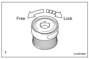
(a) Hold the center of the pulley, and confirm that the outer ring turns counterclockwise and does not turn clockwise.
If the result is not as specified, replace the clutch pulley.
2. Remove generator drive end frame bearing
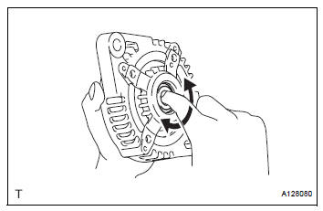
(a) Check that the bearing is not rough or worn.V
Ok: the bearing rotates smoothly.
If the bearing does not rotate smoothly, replace the bearing.
3. Inspect generator brush holder assembly
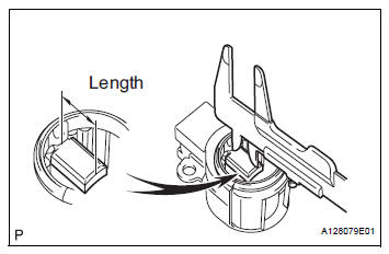
(a) Using vernier calipers, measure the length of the exposed brushes.
Standard exposed length: 9.5 to 11.5 mm (0.374 to 0.453 in.) Minimum exposed length: 4.5 mm (0.177 in.) If the exposed length is less than the minimum, replace the brush holder assembly.
4. INSPECT GENERATOR ROTOR ASSEMBLY
(a) Check that the generator rotor bearing is not rough or worn.
If necessary, replace the generator rotor assembly.
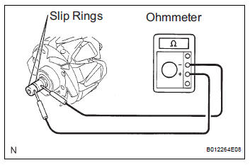
(b) Check the generator rotor for an open circuit.
(1) Using an ohmmeter, measure the resistance between the slip rings.
Standard resistance
If the result is not as specified, replace the generator rotor assembly.
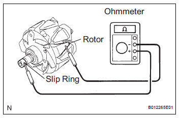
(c) Check the rotor for a short to ground.
(1) Using an ohmmeter, measure the resistance between the slip ring and rotor.
Standard resistance 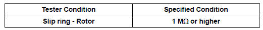
If the result is not as specified, replace the generator rotor assembly.
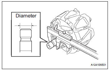
(d) Using vernier calipers, measure the slip ring diameter.
Standard diameter: 14.2 to 14.4 mm (0.559 to 0.567 in.) Minimum diameter: 14.0 mm (0.551 in.)
If the diameter is less than the minimum, replace the generator rotor assembly.
 Disassembly
1. REMOVE GENERATOR CLUTCH PULLEY
(A) using a screwdriver, remove the generator pulley
cap.
(b) Set SST (A) and (B).
SST 09820-63020
(c) Clamp SST (A) in a vise.
NOTICE:
...
 Replacement
1. REPLACE GENERATOR DRIVE END FRAME BEARING
(a) Remove the 4 screws and retainer plate from the
drive end frame.
(b) Using SST and a hammer, tap out the drive end
frame bearing from the d ...
Other materials:
Adjustment
HINT:
On the RH side, use the same procedures as on the LH
side.
Since a centering bolt is used as door hinge mounting
bolts on the body side and the door side, the door cannot
be adjusted with them on. Substitute a bolt with a washer
for the centering bolt.
1. INSPECT BACK DOOR PAN ...
Installation
1. INSTALL BRAKE ACTUATOR
NOTICE:
Do not remove the hole plugs before connecting the
brake tubes. New actuators are filled with brake
fluid.
(a) Install the brake actuator assembly with the 2 nuts.
Torque: 5.4 N*m (55 kgf*cm, 48 in.*lbf)
2. INSTALL BRAKE ACTUATOR WITH BRACKET
(a) Insta ...
Installation
1. Install speed sensor (nc sensor)
(a) Coat the O-ring with ATF.
(b) Install the speed sensor with the bolt.
Torque: 11 N*m (115 kgf*cm, 8 ft.*lbf)
HINT:
Make sure to install the same manufacturer's
sensor.
(c) Connect the speed sensor connector.
2. INSTALL SPEED SENSOR (NT SENSOR)
...
