Toyota Sienna Service Manual: Evaporative Emission Control System Pressure
DTC P0450 Evaporative Emission Control System Pressure Sensor / Switch
DTC P0451 Evaporative Emission Control System Pressure Sensor Range / Performance
DTC P0452 Evaporative Emission Control System Pressure Sensor / Switch Low Input
DTC P0453 Evaporative Emission Control System Pressure Sensor / Switch High Input
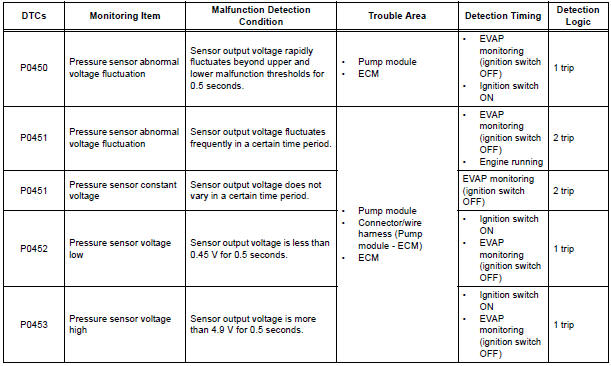
DTC SUMMARY
HINT: The canister pressure sensor is built into the canister pump module.
DESCRIPTION
The description can be found in the EVAP (Evaporative Emission) System
MONITOR DESCRIPTION
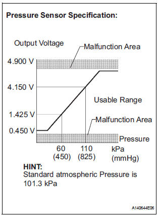
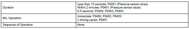
- DTC P0450: Pressure sensor abnormal voltage fluctuation If the pressure sensor voltage output rapidly fluctuates between less than 0.45 V and more than 4.9 V, the ECM interprets this as an open or short circuit malfunction in the pressure sensor or its circuit, and stops the EVAP (Evaporative Emission) system monitor. The ECM then illuminates the MIL and sets the DTC (1 trip detection logic).
- DTC P0451: Pressure sensor abnormal voltage fluctuation or being
constant
If the pressure sensor voltage output fluctuates rapidly for 10 seconds, the
ECM stops the EVAP
system monitor. The ECM interprets this as the pressure sensor voltage
fluctuating, and stops the
EVAP system monitor. The ECM then illuminates the MIL and sets the DTC.
Alternatively, if the sensor voltage output does not change for 10 seconds, the ECM interprets this as the sensor being stuck, and stops the monitor. The ECM then illuminates the MIL and sets the DTC.
(Both the malfunctions are detected by 2 trip detection logic.)
- DTC P0452: Pressure sensor voltage low If the pressure sensor voltage output is below 0.45 V, the ECM interprets this as an open or short circuit malfunction in the pressure sensor or its circuit, and stops the EVAP system monitor. The ECM then illuminates the MIL and sets the DTC (1 trip detection logic).
- DTC P0453: Pressure sensor voltage high If the pressure sensor voltage output is 4.9 V or more, the ECM interprets this as an open or short circuit malfunction in the pressure sensor or its circuit, and stops the EVAP system monitor. The ECM then illuminates the MIL and sets the DTC (1 trip detection logic).
MONITOR STRATEGY
TYPICAL ENABLING CONDITIONS
All:

P0451 (Noise monitor):
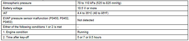
P0451 (Stuck monitor):
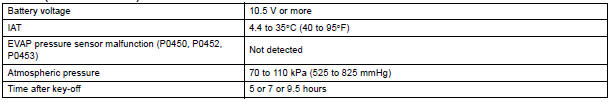
P0450, P0452 and P0453:

TYPICAL MALFUNCTION THRESHOLDS
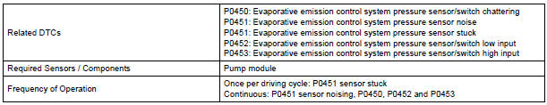
(a) P0450: Pressure sensor chattering

(b) P0451: Pressure sensor noise

(c) P0451: Pressure sensor stuck

(d) P0452: Pressure sensor low voltage

(e) P0453: Pressure sensor high voltage

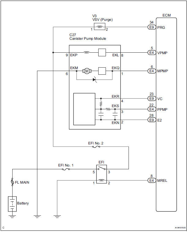
WIRING DIAGRAM
INSPECTION PROCEDURE
NOTICE:
- When a vehicle is brought into the workshop, leave it as it is. Do not change the vehicle condition. For example, do not tighten the fuel cap.
- Do not disassemble the canister pump module.
- The intelligent tester is required to conduct the following diagnostic troubleshooting procedure.
1 CONFIRM DTC AND EVAP PRESSURE
- Connect the intelligent tester to the DLC3.
- Turn the ignition switch to the ON position (do not start the engine).
- Turn the tester on.
- Select the following menu items: DIAGNOSIS / ENHANCED OBD II / DTC INFO / CURRENT CODES.
- Read DTCs.
- Select the following menu items: DIAGNOSIS / ENHANCED OBD II / DATA LIST / EVAP / EVAP VAPOR PRESS.
- Read the EVAP (Evaporative Emission) pressure displayed on the tester.
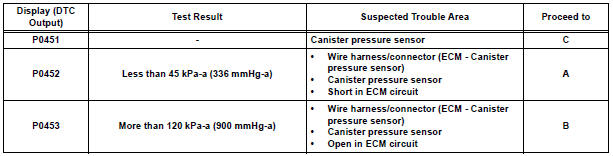
Result
2 CHECK HARNESS AND CONNECTOR (CANISTER PUMP MODULE - ECM)
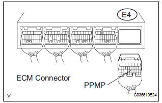
- Turn the ignition switch off.
- Disconnect the E4 ECM connector.
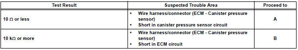
- Measure the resistance between the PPMP terminal of the ECM connector and the body ground.
Result
- Reconnect the ECM connector.
3 CHECK HARNESS AND CONNECTOR (CANISTER PUMP MODULE - ECM)
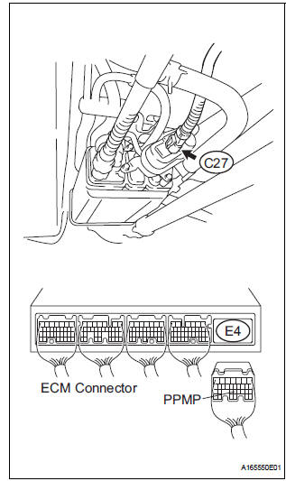
- Disconnect the C27 canister pump module connector.
- Disconnect the E4 ECM connector.
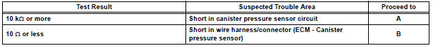
- Measure the resistance between the PPMP terminal of the ECM connector and the body ground.
Result
- Reconnect the canister pump module connector.
- Reconnect the ECM connector.
4 CHECK HARNESS AND CONNECTOR (CANISTER PUMP MODULE - ECM)
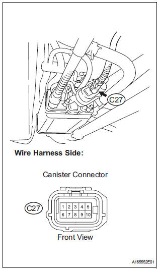
- Disconnect the C27 canister pump module connector.
- Turn the ignition switch to the ON position.
- Measure the voltage and resistance of the canister connector.
Standard
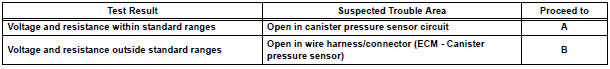
Result
- Reconnect the canister pump module connector.
5 REPLACE CHARCOAL CANISTER ASSEMBLY
- Replace the canister assembly
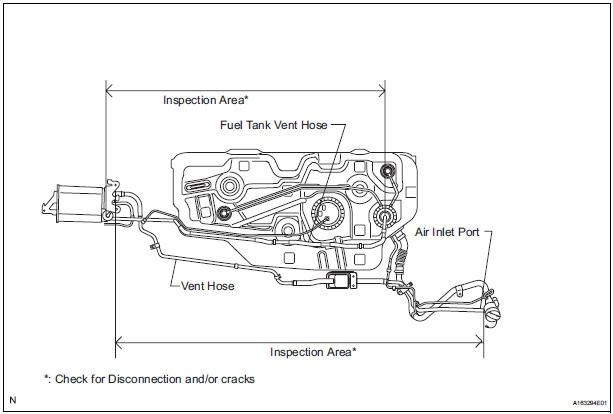
NOTICE: When replacing the canister, check the canister pump module interior and related pipes for water, fuel and other liquids. If liquids are present, check for disconnections and/or cracks in the following: 1) the pipe from the air inlet port to the canister pump module; 2) the canister filter; and 3) the fuel tank vent hose.
6 REPAIR OR REPLACE HARNESS OR CONNECTOR (CANISTER PUMP MODULE - ECM)
HINT: If the exhaust tailpipe has been removed, go to the next step before reinstalling it.
7 REPLACE ECM
- Replace the ECM
8 CHECK WHETHER DTC OUTPUT RECURS (AFTER REPAIR)
- Connect the intelligent tester to the DLC3.
- Turn the ignition switch to the ON position and turn the tester on.
- Wait for at least 60 seconds.
- On the tester, select the following menu items: DIAGNOSIS / ENHANCED OBD II / DTC INFO / PENDING CODES.
HINT: If no pending DTCs are displayed on the tester, the repair has been successfully completed.
COMPLETED
 Evaporative Emission Control System Incorrect
Purge Flow
Evaporative Emission Control System Incorrect
Purge Flow
DTC P0441 Evaporative Emission Control System Incorrect
Purge Flow
DTC SUMMARY
DESCRIPTION
The circuit description can be found in the EVAP (Evaporative Emission)
System.
INSPECTION PROCEDU ...
 Evaporative Emission Control System Leak
Detected
Evaporative Emission Control System Leak
Detected
DTC P0455 Evaporative Emission Control System Leak
Detected (Gross Leak)
DTC P0456 Evaporative Emission Control System Leak
Detected (Very Small Leak)
DTC SUMMARY
DESCRIPTION
The circuit des ...
Other materials:
CAN Bus Line
DESCRIPTION
When any DTC for the CAN communication system is output, first measure the
resistance between the
terminals of the DLC3 to specify the trouble area, and check that there is no
short in the CAN main wire,
between the main wire, and +B or GND.
WIRING DIAGRAM
INSPECTION PRO ...
Shifting the shift lever
While the engine switch is in the
“ON” position (vehicles without a
smart key system) or IGNITION ON mode (vehicles with a smart
key system), move the shift lever with the brake pedal
depressed.
When shifting the shift lever between P and D, make sure that the vehicle
is completely ...
Route cannot be Calculated
INSPECTION PROCEDURE
1 CHECK MAP DISC
Check that the map disc is not deformed or cracked.
OK:
No deformations or cracks on map disc.
2 SET DESTINATION
Set another destination and check if the system can
calculate the route correctly.
OK:
Route can be correctly calculated.
NO ...
