Toyota Sienna Service Manual: Heated oxygen sensor (for 2wd)
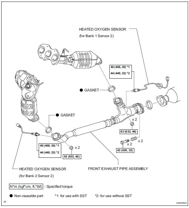
Components
Removal
1. DISCONNECT CABLE FROM NEGATIVE BATTERY TERMINAL
| CAUTION: Wait at least 90 seconds after disconnecting the cable from the nagative (-) battery terminal to prevent airbag and seat belt pretensioner activation. |
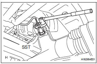
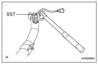
2. REMOVE HEATED OXYGEN SENSOR (for Bank 1 Sensor 2)
(a) Disconnect the sensor connector under the center console.
(b) Using SST, remove the heated oxygen sensor.
SST 09224-00010
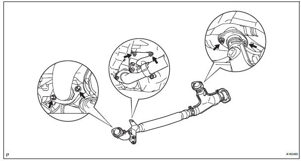
3. REMOVE FRONT EXHAUST PIPE ASSEMBLY
(a) Disconnect the heated oxygen sensor (for Bank 2 Sensor 2) connector.
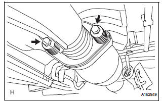
(b) Remove the 2 bolts and 2 compression springs.
(c) Remove the 6 nuts and front exhaust pipe assembly.
4. REMOVE HEATED OXYGEN SENSOR (for Bank 2 Sensor 2)
(a) Using SST, remove the heated oxygen sensor from the front exhaust pipe assembly.
SST 09224-00010
 Installation
1. INSTALL AIR FUEL RATIO SENSOR (for Bank 2
Sensor 1)
(a) Using SST, install the sensor to the exhaust
manifold LH.
SST 09224-00010
Torque: 40 N*m (408 kgf*cm, 30 ft.*lbf) for use
with SST
...
 Inspection
1. INSPECT HEATED OXYGEN SENSOR (for Bank 1
Sensor 2)
(a) Measure the resistance of the sensor.
Standard resistance
If the resistance is not as specified, replace the
sensor.
2. INSPECT HE ...
Other materials:
VSC Warning Light does not Come ON
DESCRIPTION
The skid control ECU is connected to the combination meter via CAN and
multiplex communications.
If the skid control ECU stores DTCs to shut down TRAC and VSC operation, the VSC
warning light comes
on in the combination meter.
WIRING DIAGRAM
Refer to VSC Warning Light Remains ...
Removal
1. REMOVE ENGINE ASSEMBLY WITH TRANSAXLE
HINT:
See page EM-26
2. SECURE ENGINE (See page EM-37)
3. REMOVE GENERATOR ASSEMBLY (See page CH-17)
4. REMOVE COMPRESSOR AND MAGNETIC CLUTCH
(See page AC-227)
5. REMOVE NO. 1 ENGINE FRONT MOUNTING
BRACKET LH (See page EM-42)
6. REMOVE NO. 2 IDLER PU ...
Open in Side Squib LH Circuit
DTC B0116/48 Open in Side Squib LH Circuit
DESCRIPTION
The side squib LH circuit consists of the center airbag sensor assembly and
the front seat side assembly
LH.
This circuit instructs the SRS to deploy when deployment conditions are met.
DTC B0116/48 is recorded when an open circuit is ...
