Toyota Sienna Service Manual: Removal
1. REMOVE ENGINE ASSEMBLY WITH TRANSAXLE
HINT: See page EM-26
2. SECURE ENGINE (See page EM-37) 3. REMOVE GENERATOR ASSEMBLY (See page CH-17) 4. REMOVE COMPRESSOR AND MAGNETIC CLUTCH (See page AC-227) 5. REMOVE NO. 1 ENGINE FRONT MOUNTING BRACKET LH (See page EM-42) 6. REMOVE NO. 2 IDLER PULLEY SUB-ASSEMBLY
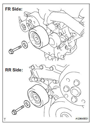
(a) Remove the 2 bolts, 2 idler pulley cover plates and 2 idler pulley sub-assemblies.
7. REMOVE V-RIBBED BELT TENSIONER ASSEMBLY
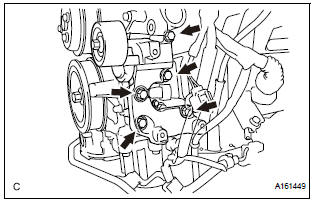
(a) Remove the 5 bolts and V-ribbed belt tensioner assembly.
8. REMOVE WATER PUMP PULLEY
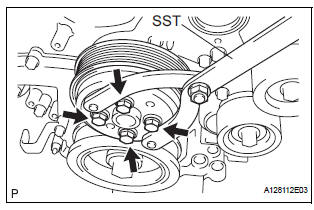
(a) Using SST, hold the water pump pulley.
SST 09960-10010 (09962-01000, 09963-00700) (b) Remove the 4 bolts and water pump pulley.
9. REMOVE WATER INLET HOUSING
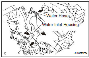
(a) Disconnect the water hose.
(b) Remove the 2 bolts, nut and water inlet housing.
(c) Remove the water inlet housing gasket and water outlet pipe O-ring.
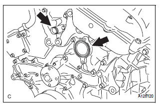
10. REMOVE WATER PUMP ASSEMBLY
(a) Remove the 16 bolts, water pump assembly and water pump gasket.
 Water pump
COMPONENTS
...
 Inspection
1. Inspect water pump assembly
(a) Visually check the drain hole and air hole for coolant
leakage.
(b) Turn the pulley, and check that the water pump
bearing moves smoothly and noiselessly.
...
Other materials:
Monitor drive pattern
1. MONITOR DRIVE PATTERN FOR ECT TEST
(a) Perform this drive pattern as one method to
simulate the detection conditions of the ECT
malfunctions. (The DTCs may not be detected due
the actual driving conditions. And some codes may
not be detected through this drive pattern.)
HINT:
Preparation f ...
Entire Combination Meter does not Operate
DESCRIPTION
This is the power source circuit to operate the combination meter assembly.
WIRING DIAGRAM
INSPECTION PROCEDURE
1 INSPECT COMBINATION METER ASSEMBLY
Disconnect the C10 connector.
Measure the resistance according to the value(s) in the
table below.
Standard resistan ...
Power back door drive unit
INSPECTION
1. INSPECT POWER BACK DOOR DRIVE UNIT
Remove the unit.
Apply battery voltage to the terminals and check the
motor operation.
Standard
If the result is not as specified, replace the drive
unit.
Check the resistance of the clutch terminals.
Resistance
If th ...
