Toyota Sienna Service Manual: IG Power Source Circuit
DESCRIPTION
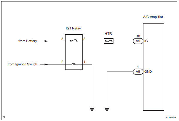
The main power source is supplied to the A/C amplifier when the ignition switch is turned to the ON position.
The power source is used for operating the A/C amplifier and servo motor, etc.
WIRING DIAGRAM
INSPECTION PROCEDURE
HINT: Start the engine before inspection. Check the IG1 relay or battery if the engine does not start.
1 INSPECT FUSE (HTR)
(a) Remove the HTR fuse from the driver side junction block.
(b) Measure the resistance according to the value(s) in the table below.
Standard resistance 


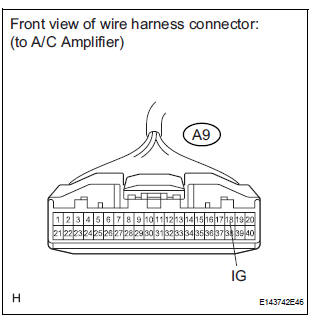
2 INSPECT A/C AMPLIFIER (IG - GND)
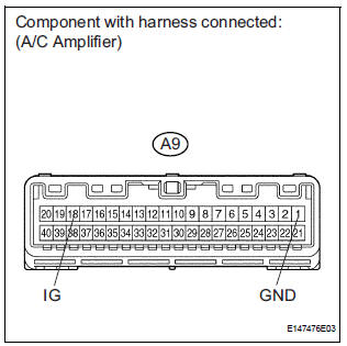
(a) Remove the A/C amplifier with its connectors still connected.
(b) Turn the ignition switch to the ON position.
(c) Measure the voltage according to the value(s) in the table below.
Standard voltage 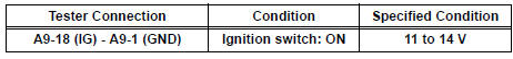


PROCEED TO NEXT CIRCUIT INSPECTION SHOWN IN PROBLEM SYMPTOMS TABLE
3 CHECK HARNESS AND CONNECTOR (A/C AMPLIFIER - BATTERY)
(a) Disconnect the connector from the A/C amplifier.
(b) Measure the voltage according to the value(s) in the table below.
Standard voltage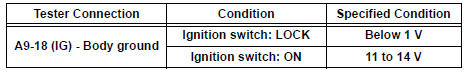

4 CHECK HARNESS AND CONNECTOR (A/C AMPLIFIER - BODY GROUND)
(a) Measure the resistance according to the value(s) in the table below.
Standard resistance 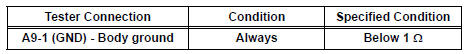

REPLACE A/C AMPLIFIER
 Rear Blower Motor Circuit
DESCRIPTION
Power to the rear blower motor is supplied from the battery via the RR A/C
relay.
The rear blower motor speed level varies between 0 and 31 based on the voltage
difference measured ...
 ACC Power Source Circuit
DESCRIPTION
This circuit supplies power to the A/C amplifier and the illumination for the
clock.
WIRING DIAGRAM
INSPECTION PROCEDURE
1 INSPECT FUSE (ECU ACC)
(a) Remove the ECU ACC fuse fr ...
Other materials:
Diagnosis system
1. DESCRIPTION
(a) When troubleshooting OBD II vehicles, the only
difference from the usual troubleshooting procedure
is to connect an OBD II scan tool complying with
SAE J1987 or a intelligent tester to the vehicle, and
read off various data output from the vehicle's ECM.
(b) OBD II reg ...
On-vehicle inspection
1. INSPECT SEAT POSITION SENSOR (VEHICLE NOT
INVOLVED IN COLLISION)
Perform a diagnostic system check.
2. INSPECT SEAT POSITION SENSOR (VEHICLE
INVOLVED IN COLLISION)
Perform a diagnostic system check.
Even if the airbag was not deployed, check if there
is any dama ...
Smart key system
The following operations can be performed simply by carrying
the electronic key on your person, for example in your pocket.
The driver should always carry the electronic key.
Locks and unlocks the doors
Front door handles
Sliding door handles
Back door
Starts and stops the ...
