Toyota Sienna Service Manual: Rear Blower Motor Circuit
DESCRIPTION
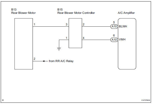
Power to the rear blower motor is supplied from the battery via the RR A/C relay.
The rear blower motor speed level varies between 0 and 31 based on the voltage difference measured between the terminals of the motor.
The voltage difference measured between the terminals of the rear blower motor changes in proportion to the control at the rear blower motor controller on the ground side.
WIRING DIAGRAM
INSPECTION PROCEDURE
1 READ VALUE OF INTELLIGENT TESTER
(a) Connect the intelligent tester to the DLC3.
(b) Turn the ignition switch to the ON position and turn the intelligent tester main switch on.
(c) Select the item below in the DATA LIST, and read the display on the intelligent tester.
DATA LIST / AIR CONDITIONER 
OK: The display is as specified in the normal condition.

PROCEED TO NEXT CIRCUIT INSPECTION SHOWN IN PROBLEM SYMPTOMS TABLE
2 INSPECT REAR BLOWER MOTOR
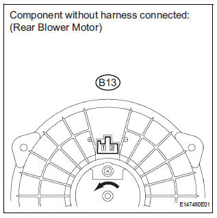
(a) Remove the rear blower motor with the connector still connected.
(b) Disconnect the connector from the rear blower motor.
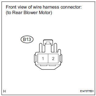
(c) Connect the positive (+) lead to terminal 1 of the rear blower motor connector, and the negative (-) lead to terminal 2.
OK: The rear blower motor operates smoothly.


3 CHECK HARNESS AND CONNECTOR (REAR BLOWER MOTOR - BATTERY)
(a) Measure the voltage according to the value(s) in the table below.
Standard voltage 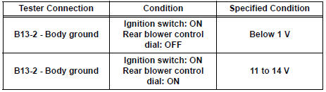
4 CHECK HARNESS AND CONNECTOR (REAR BLOWER MOTOR CONTROLLER - BODY GROUND)
(a) Disconnect the connector from the rear blower motor controller.
(b) Measure the resistance according to the value(s) in the table below.
Standard resistance 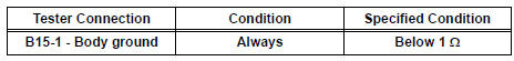

5 CHECK HARNESS AND CONNECTOR (REAR BLOWER MOTOR - REAR BLOWER MOTOR CONTROLLER)
(a) Measure the resistance according to the value(s) in the table below.
Standard resistance 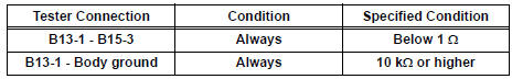

6 CHECK HARNESS AND CONNECTOR (REAR BLOWER MOTOR CONTROLLER - A/C AMPLIFIER)
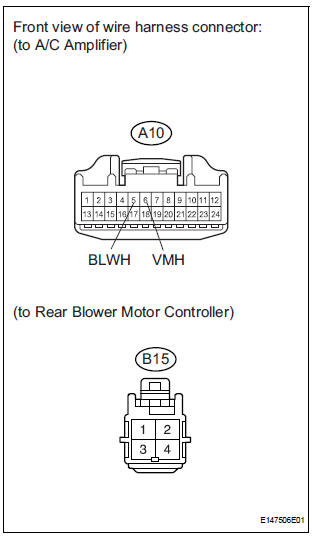
(a) Disconnect the connector from the A/C amplifier.
(b) Measure the resistance according to the value(s) in the table below.

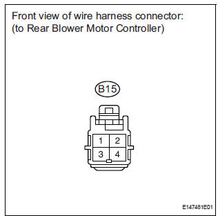
7 INSPECT REAR BLOWER MOTOR CONTROLLER
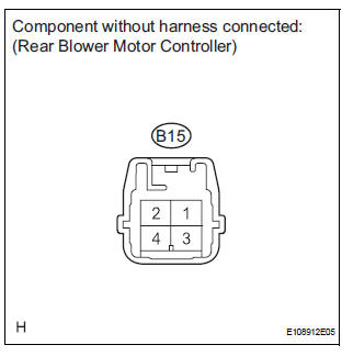
(a) Disconnect the connector from the rear blower motor controller.
(b) Measure the resistance according to the value(s) in the table below.
Standard resistance 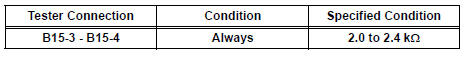
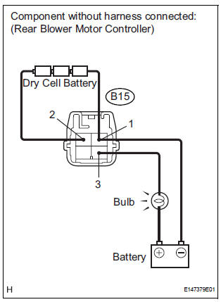
(c) Connect the positive (+) lead to terminal 3 through a 12 V 3.4 W test bulb, and the negative (-) lead to terminal 1.
(d) Connect the three 1.5 V dry cell batteries' positive (+) lead to terminal 2, and the negative (-) lead to terminal 1.
Then check that the test bulb comes on.
OK: The test bulb comes on.

PROCEED TO NEXT CIRCUIT INSPECTION SHOWN IN PROBLEM SYMPTOMS TABLE
 Rear Air Conditioning Relay Circuit
DESCRIPTION
The RR A/C relay is switched on by signals from the A/C amplifier. It
supplies power to the rear blower
motor.
WIRING DIAGRAM
INSPECTION PROCEDURE
1 INSPECT RELAY (RR A/C)
...
 IG Power Source Circuit
DESCRIPTION
The main power source is supplied to the A/C amplifier when the ignition
switch is turned to the ON
position.
The power source is used for operating the A/C amplifier and servo moto ...
Other materials:
For vehicles equipped with srs airbag and seat belt pretensioner
The SIENNA is equipped with a Supplemental Restraint System (SRS).
CAUTION: Failure to carry out the service operations in the correct sequence could cause the SRS to unexpectedly deploy during servicing and lead to serious injury. Furthermore, if a mistake is made when servicing SRS, it is poss ...
Light Sensor Circuit Malfunction
DTC B1244 Light Sensor Circuit Malfunction
DESCRIPTION
This DTC is output when failure in the light sensor circuit is detected.
DTC No.
DTC Detection Condition
Trouble Area
B1244
Malfunction of automatic light control sensor
Open or short of a ...
Ambient temperature sensor circuit
DTC B1412/12 Ambient Temperature Sensor Circuit
DESCRIPTION
The ambient temperature sensor is installed in front of the condenser to
detect the ambient temperature
which is used to control the air conditioner "AUTO" mode. This sensor is
connected to the A/C amplifier
and detects fl ...
