Toyota Sienna Service Manual: Inspection
1. INSPECT PACK CLEARANCE OF FORWARD CLUTCH
(a) Install the forward clutch on the oil pump.
NOTICE: Be careful not to damage the oil seal ring of oil pump.
b) Using a dial indicator, measure the forward clutch pack clearance while applying and releasing compressed air (392 kPa, 4.0 kgf/cm2, 57 psi).
Pack clearance: 1.00 to 1.25 mm (0.0394 to 0.4921 in.)
If the clearance is not as specified, inspect the discs, plates and flange.
HINT: If the opening is large, cover it with a shop rug or a piece of cloth to prevent the compressed air from being released.
2. INSPECT FORWARD MULTIPLE DISC CLUTCH DISC
(a) Check if the sliding surface of the disc, plate and flange are worn or burnt.
If necessary, replace them.
HINT:
- If the lining of the disc comes off or discolors, or if a part of the groove is worn, replace all discs.
- Before installing new discs, immerse them in ATF for at least 15 minutes.
3. INSPECT FORWARD CLUTCH RETURN SPRING SUB-ASSEMBLY
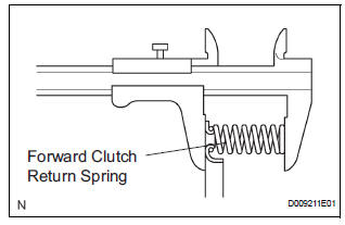
(a) Using vernier calipers, measure the free length of the spring together with the spring seat.
Standard free length: 26.74 mm (1.0528 in.)
4. INSPECT PACK CLEARANCE OF FORWARD CLUTCH
(a) Using a dial indicator, measure the forward clutch pack clearance while applying and releasing compressed air (392 kgf/cm2, 4.0 kPa, 57 psi).
Pack clearance: 1.00 to 1.25 mm (0.0394 to 0.4921 in.)
If the piston stroke is less than the minimum, parts may be assembled incorrectly. Check and reassemble the parts again.
If the clearance is not as specified, select another flange.
HINT: There are 5 different thicknesses of flanges available.
Flange thickness: mm (in.)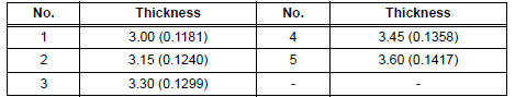
5. INSPECT FORWARD MULTIPLE DISC CLUTCH DISC
(a) Check if the disc lightly rotates when rotating the forward clutch assembly after inserting the multiple disc clutch into it.
NOTICE: Do not place the forward clutch assembly in a vise.
 Disassembly
1. INSPECT PACK CLEARANCE OF FORWARD
CLUTCH
HINT:
(See page AX-242)
2. REMOVE FORWARD MULTIPLE DISC CLUTCH DISC
(a) Using a screwdriver, remove the snap ring.
(b) Remove the flange, 5 di ...
 Reassembly
1. INSTALL INPUT SHAFT OIL SEAL RING
(a) Compress a new input shaft oil seal ring from both
sides to reduce dimension A.
Dimension A:
5 mm (0.197 in.)
(b) Coat the oil seal ring with ATF and ...
Other materials:
Summary of functions
Dynamic radar cruise control supplements conventional cruise control
with a vehicle-to-vehicle distance control. In vehicle-to-vehicle distance
control mode, the vehicle automatically accelerates or decelerates
in order to maintain a set following distance from vehicles ahead.
Multi-infor ...
Folding Motor Circuit
DESCRIPTION
The fold seat control ECU receives a switch operation signal from the fold
seat switch and activates the
folding motor. At this time, the Hall IC (seat cushion position sensor) detects
the actuation signal. The fold
seat control ECU uses signals from the Hall IC (seat cushion posi ...
Glove boxes
Upper glove box
Push the button.
Open the lid.
Lower glove box
The lower glove box can be opened by pulling the lever and can be
locked and unlocked by using the master key (vehicles without a
smart key) or the mechanical key (vehicles with a smart key system).
Unlo ...
