Toyota Sienna Service Manual: Inspection
1. INSPECT FRONT DIFFERENTIAL
(a) Using a dial indicator, measure the backlash of one pinion gear while holding the front differential side gear toward the case.
Standard backlash: 0.05 - 0.20 mm (0.0020 - 0.0079 in.)
NOTICE: Do not mount the surface of front differential case which contacts with bushing in a vise.
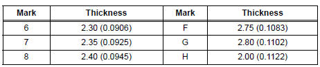
If the backlash is not within the specified value, refer to the table below and select a thrust washer which will ensure that the backlash is within the specified value.
Thrust washer thickness: mm (in.)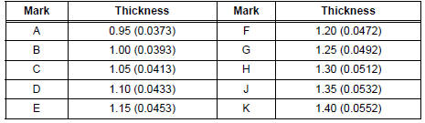
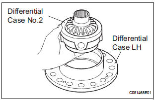
(b) Engage the front differential side to the above mentioned front differential case.
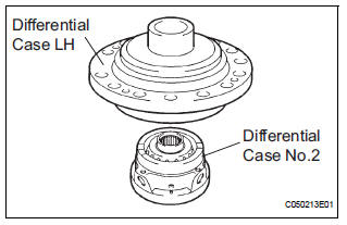
(c) Install the differential case LH to the front differential case and measure its center.
(d) After that, remove the differential case LH.
(e) Using a straight edge and feeler gauge, measure the clearance between the front differential case and the front differential side gear.
HINT:
- t= Thrust washer thickness
- L= Clearance
- t= L-0.162 - 0.265 mm (0.0064 - 0.0104 in.)
If the clearance is not within the specified value, refer to the table below and select a thrust washer which will ensure that the clearance is within the specified value.
Thrust washer thickness: mm (in.)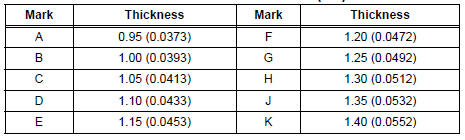
If the clearance is not within the specified value, parts may have been assembled incorrectly, so check and reassemble it.
2. INSPECT CENTER DIFFERENTIAL
(a) Pressing and holding the differential spider toward the differential case RH, measure the pinion's backlash with a dial indicator as illustrated.
Standard backlash: 0.05 - 0.20 mm (0.0020 - 0.0079 in.)
If the backlash is not within the specified value, refer to the table below and select a thrust washer which will ensure that the backlash is within the specified value.
Thrust washer thickness: mm (in.)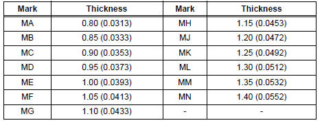
b) Temporarily install the differential side gear thrust washer No.2 LH, center differential side gear conical spring washer and differential case No.2 to the differential case LH.
HINT: Ensure that the conical washers is installed correctly.
(c) Install the differential intermediate case to the above and fix them with 4 bolts.
(d) remove the differential spider, 5 center differential pinions and 5 center differential pinion thrust washers from the differential case RH. Put them in the differential intermediate case and fix the case.
(e) Pressing and holding the differential spider toward the differential intermediate case, measure the pinion's backlash with a dial indicator.
Standard backlash: 0.05 - 0.20 mm (0.0020 - 0.0079 in.)
If the backlash is not within the specified value, refer to the table below and select a thrust washer which will ensure that the backlash is within the specified value.
Thrust washer thickness: mm (in.)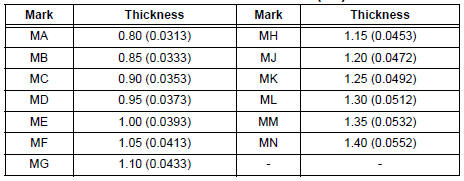
(f) Remove the 4 bolts and disconnect the differential case LH from the differential intermediate case.
(g) Remove the differential case No.2 from the differential case LH.
3. ADJUST TAPERED ROLLER BEARING PRELOAD
(a) Install the intermediate case to the differential case LH and fix them with 4 bolts.
(b) Install the differential assembly to the transaxle case.
(c) Clean the matching surfaces of the transaxle case and transaxle housing.
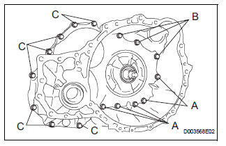
(d) Install the transaxle housing to the transaxle case and tighten them with the 16 bolts.
Torque: Bolt A 25 N*m (255 kgf*cm, 18 ft.*lbf) Bolt B 33 N*m (337 kgf*cm, 24 ft.*lbf) Bolt C 29 N*m (295 kgf*cm, 21 ft.*lbf)
Bolt length: Bolt A: 50 mm (1.969 in.) Bolt B: 50 mm (1.969 in.) Bolt C: 42 mm (1.654 in.)
HINT: Usually, bolt A is a non-reusable bolt. In the case, however, it can be used after cleaning it.
(e) Using SST, turn the differential assembly right and left 2 or 3 times to allow the bearing settle.
SST 09564-32011
(f) Using SST and a torque wrench, measure the turning torque of the differential case assembly.
SST 09564-32011 Torque: New bearing (*) 0.2 to 0.69 N*m (2.0 to 7.0 kgf*cm, 1.8 to 601 in.*lbf) Used bearing (*) 0.10 to 0.35 N*m (1.0 to 3.6 kgf*cm, 0.9 to 3.1 in.*lbf)
HINT:
- (*): Turning torque at 60 rpm
- If the turning torque is not within the specified value, refer to the table below and select a thrust washer which turning torque is within the specified value.
Flange thickness: mm (in.)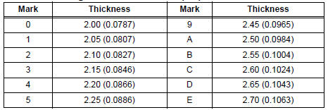
(g) Remove the 16 bolts and the transaxle housing.
(h) Remove the differential assembly.
 Disassembly
1. REMOVE FRONT DIFFERENTIAL RING GEAR
(a) Place the match-marks on the ring gear and
differential case.
(b) Remove the 16 bolts.
(c) Using a plastic hammer, tap ring gear to remove it ...
 Reassembly
1. INSTALL DIFFERENTIAL CASE SUB-ASSEMBLY NO.2
(a) Coat the front differential side gear thrust washer
No.1, front differential planetary ring gear, front
differential pinion No.2, front differ ...
Other materials:
GPS Antenna Error/ GPS Antenna Power Source Error
DTC 58-40 GPS Antenna Error
DTC 58-41 GPS Antenna Power Source Error
DTC 80-40 GPS Antenna Error
DTC 80-41 GPS Antenna Power Source Error
DESCRIPTION
DTC No.
DTC Detection Condition
Trouble Area
58-40
GPS antenna error
Wire harness
GPS ...
Reassembly
1. INSTALL TRANSFER DRIVEN PINION REAR BEARING
(a) Using SST(s) and a press, install the transfer driven
pinion rear bearing outer race to the transfer case.
SST 09950-60010 (09951-00620), 09950-70010
(09951-07150)
NOTICE:
Place something like wood blocks under the
case to keep its level. ...
Knock sensor
COMPONENTS
REMOVAL
1. DISCHARGE FUEL SYSTEM PRESSURE
(See page FU-13)
2. REMOVE V-BANK COVER SUB-ASSEMBLY (See
page EM-28)
3. DRAIN ENGINE COOLANT (See page CO-6)
4. REMOVE WINDSHIELD WIPER MOTOR ASSEMBLY
HINT:
(See page WW-4)
5. REMOVE FRONT OUTER COWL TOP PANEL SUBASSEMBLY
( ...
