Toyota Sienna Service Manual: Installation
1. INSTALL SLIDE DOOR ROLLER ASSEMBLY UPPER
- Apply MP grease to the rotating areas of the roller.
- Install the roller with the 2 bolts.
Torque: 13 N*m (130 kgf*cm, 10 ft.*lbf)
2. INSTALL SLIDE DOOR HINGE ASSEMBLY CENTER LH
- Apply MP grease to the rotating areas of the hinge.
- Install the hinge with the 3 bolts.
Torque: 31 N*m (316 kgf*cm, 23 ft.*lbf)
3. INSTALL SLIDE DOOR ROLLER ASSEMBLY LOWER LH
- Apply MP grease to the rotating areas of the roller.
- Install the roller lower with the 3 bolts.
Torque: 31 N*m (316 kgf*cm, 23 ft.*lbf)
4. INSTALL SLIDE DOOR FULL OPEN STOP LOCK ASSEMBLY LH
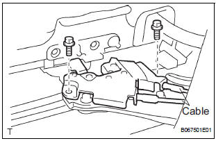
- Apply MP grease to the sliding and rotating areas of the lock.
- Install the lock with the 2 bolts.
Torque: 8.0 N*m (82 kgf*cm, 71 in.*lbf)
- Connect the 2 cables.
5. INSTALL SLIDE DOOR RAILS
- Install the rail center with the 3 screws.
Torque: 26 N*m (265 kgf*cm, 19 ft.*lbf)
- Install the rear side rail with the 2 screws.
Torque: 19.5 N*m (200 kgf*cm, 14 ft.*lbf)
- Install the rail upper with the 2 bolts and 2 nuts.
Torque: 10 N*m (102 kgf*cm, 8 ft.*lbf)
- Install the roof headlining (See page IR-14).
6. INSTALL SLIDE DOOR
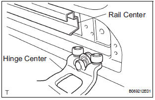
- Put in the slide door hinge center from the rear part of the slide door rail center.
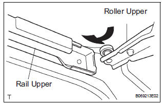
- Move the slide door forward and then put in the slide door roller upper into the cut area of the slide door rail upper
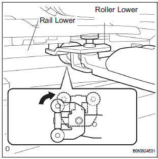
- Rotate the base of the slide door roller lower in the direction indicated by arrow in the illustration and then put in the roller lower into the cut area of the rail lower of the body.
- Install the open stop with the 2 nuts.
Torque: 7.0 N*m (71 kgf*cm, 62 in.*lbf)
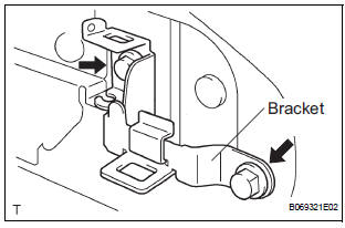
- Install the bracket center No. 2 with the 2 bolts.
Torque: 7.0 N*m (71 kgf*cm, 62 in.*lbf)
- Install the rail end moulding.
- Install the upper rail cushion to the rail upper.
- Install the wire with the bolt.
Torque: 7.0 N*m (71 kgf*cm, 62 in.*lbf)
- Connect the 2 connectors.
7. REPLACE SLIDE DOOR HALF OPEN STOPPER SUBASSEMBLY
- Install the half open stopper with the 2 bolts.
Torque: 7.0 N*m (71 kgf*cm, 62 in.*lbf)
- Connect the control cable to the half open stopper.
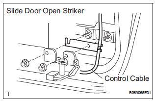
- Connect the control cable to the open striker with
the 2 nuts.
Torque: 7.0 N*m (71 kgf*cm, 62 in.*lbf)
8. REPLACE SLIDE DOOR HALF OPEN STOPPER CONTROL ASSEMBLY
- Install the control cable, as shown in the illustration.
Dimension (A): 3.9 +- 1.5 mm (0.154 +- 0.059 in.)
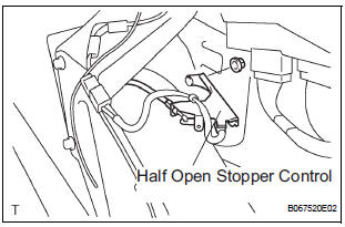
- Install the half open stopper control with the 2 nuts.
Torque: 7.0 N*m (71 kgf*cm, 62 in.*lbf)
9. REPLACE SLIDE DOOR OPEN STRIKER LH
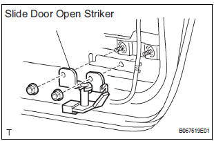
- Install the open striker with the 2 nuts.
Torque: 7.0 N*m (71 kgf*cm, 62 in.*lbf)
10. REPLACE SLIDE DOOR OPEN STRIKER RH
HINT: Use the same procedures for the LH side.
11. REPLACE SLIDE DOOR OPEN STOP LH
- Install the open stop with the 2 nuts.
Torque: 7.0 N*m (71 kgf*cm, 62 in.*lbf)
12. REPLACE SLIDE DOOR OPEN STOP RH
HINT: Use the same procedures for the LH side.
 Reassembly
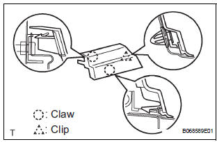
1. INSTALL REAR DOOR WIRE SUB-ASSEMBLY LH
Install the wire.
NOTICE:
When installing the wire, push the areas where
the clips are installed in order to prevent
damage and deformation.
...
 Slide door lock release motor
Inspection
1. INSPECT SLIDE DOOR LOCK RELEASE MOTOR ASSEMBLY LH
Apply battery voltage and inspect operation of the
motor.
OK
If the result is not as specified, replace the motor
as ...
Other materials:
On-vehicle inspection
1. INSPECT OCCUPANT CLASSIFICATION ECU
(VEHICLE NOT INVOLVED IN COLLISION)
Perform a diagnostic system check.
2. INSPECT OCCUPANT CLASSIFICATION ECU
(VEHICLE INVOLVED IN COLLISION)
Perform a diagnostic system check.
Even if the airbag was not deployed, check if there ...
Disassembly
1. REMOVE REAR DIFFERENTIAL CARRIER COVER
(a) Remove the 8 bolts from the carrier cover.
(b) Using a brass bar and a hammer, separate the
carrier cover from rear differential carrier assembly.
(c) Remove the breather plug from the rear differential
carrier cover.
(d) Remove the bol ...
Crankshaft Position - Camshaft Position Correlation
DTC P0016 Crankshaft Position - Camshaft Position Correlation
(Bank 1 Sensor A)
DTC P0017 Crankshaft Position - Camshaft Position Correlation
(Bank 1 Sensor B)
DTC P0018 Crankshaft Position - Camshaft Position Correlation
(Bank 2 Sensor A)
DTC P0019 Crankshaft Position - Camshaft Position Corr ...
