Toyota Sienna Service Manual: Installation
1. INSTALL WATER PUMP ASSEMBLY
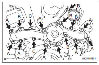
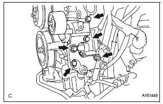
(a) Install a new water pump gasket and the water pump assembly with the 16 bolts.
Torque: Bolt A 21 N*m (214 kgf*cm, 15 ft.*lbf) Bolts B and C 9.1 N*m (93 kgf*cm, 81 in.*lbf)
NOTICE:
|
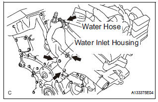
2. INSTALL WATER INLET HOUSING
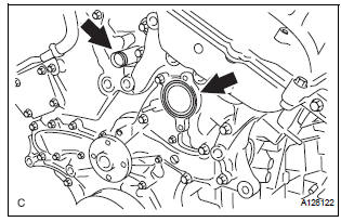
(a) Install a new water inlet housing No. 1 gasket and water outlet pipe O-ring.
(b) Install the water inlet housing with the 2 bolts and nut.
Torque: 10 N*m (102 kgf*cm, 7 ft.*lbf)
| NOTICE: Be careful not to allow the O-ring to get caught between the parts. |
(c) Connect the water hose.
3. INSTALL WATER PUMP PULLEY
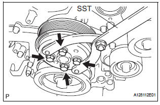
(a) Temporarily install the water pump pulley with the 4 bolts.
(b) Using SST, hold the water pump pulley.
SST 09960-10010 (09962-01000, 09963-00700) (c) Tighten the 4 bolts.
Torque: 21 N*m (214 kgf*cm, 15 ft.*lbf)
4. INSTALL V-RIBBED BELT TENSIONER ASSEMBLY
(a) Install the V-ribbed belt tensioner assembly with the 5 bolts.
Torque: 43 N*m (438 kgf*cm, 32 ft.*lbf)
5. INSTALL NO. 2 IDLER PULLEY SUB-ASSEMBLY
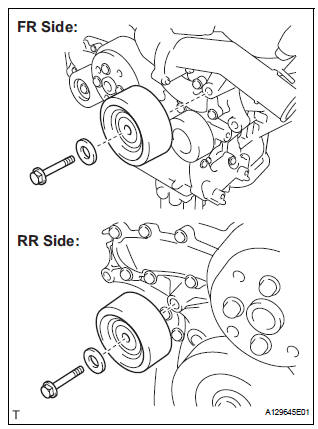
(a) Install the 2 idler pulley cover plates and idler pulley sub-assemblies with the 2 bolts.
Torque: 43 N*m (438 kgf*cm, 32 ft.*lbf)
6. INSTALL NO. 1 ENGINE FRONT MOUNTING BRACKET LH (See page EM-45) 7. INSTALL GENERATOR ASSEMBLY (See page CH-26) 8. INSTALL COMPRESSOR AND MAGNETIC CLUTCH (See page AC-231) 9. INSTALL ENGINE HANGERS (See page EM-50) 10. REMOVE ENGINE STAND 11. INSTALL ENGINE ASSEMBLY WITH TRANSAXLE HINT: See page EM-44 12. ADD ENGINE COOLANT (See page CO-7) 13. INSPECT FOR COOLANT LEAK (See page CO-1)
 Inspection
1. Inspect water pump assembly
(a) Visually check the drain hole and air hole for coolant
leakage.
(b) Turn the pulley, and check that the water pump
bearing moves smoothly and noiselessly.
...
 Thermostat
Components
...
Other materials:
Throttle Actuator Control Motor Current Range
/ Performance
DTC P2118 Throttle Actuator Control Motor Current Range
/ Performance
DESCRIPTION
The ETCS (Electronic Throttle Control System) has a dedicated power supply
circuit. The voltage (+BM)
is monitored and when it is low (less than 4 V), the ECM determines that there
is a malfunction in the
ETCS ...
Description of code registration
It is necessary to register the transmitter ID in the tire
pressure warning ECU when replacing the tire pressure
warning valve and transmitter and/or tire pressure
warning ECU.
(a) Before registration
(1) In case of tire pressure warning ECU
replacement.
Read the registered transmitter I ...
A/F Sensor Circuit Slow Response
HINT:
DTC P2A00 indicates malfunctions related to the bank 1 A/F sensor.
DTC P2A03 indicates malfunctions related to the bank 2 A/F sensor.
Bank 1 refers to the bank that includes cylinder No. 1.
Bank 2 refers to the bank that includes cylinder No. 2.
Sensor 1 refers to the sensor mo ...
