Toyota Sienna Service Manual: Installation
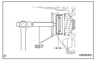
1. INSTALL TRANSAXLE HOUSING OIL SEAL
(a) Using SST and a hammer, install a new oil seal.
SST 09316-60011 (09316-00011) Oil seal installation depth: -0.5 to 0.5 mm (-0.020 to 0.020 in.) (b) Coat the lip of the oil seal with MP grease.
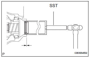
2. INSTALL DIFFERENTIAL SIDE BEARING RETAINER OIL SEAL
(a) Using SST and a hammer, install a new oil seal.
SST 09223-15020, 09950-70010 (09951-07150) Oil seal installation depth: -0.5 to 0.5 mm (-0.020 to 0.020 in.) (b) Coat the lip of the oil seal with MP grease.
3. INSTALL FRONT DRIVE SHAFT ASSEMBLY LH
HINT: (See page DS-17)
4. INSTALL FRONT DRIVE SHAFT ASSEMBLY RH (for 2WD)
HINT: (See page DS-17)
5. INSTALL FRONT WHEELS Torque: 103 N*m (1,050 kgf*cm, 76 ft.*lbf) 6. ADD AUTOMATIC TRANSAXLE FLUID 7. INSPECT AUTOMATIC TRANSAXLE FLUID (See page AX-123) 8. INSTALL ENGINE UNDER COVER NO.1 9. CHECK ABS SPEED SENSOR SIGNAL
HINT: (See page BC-82)
 Removal
1. REMOVE FRONT WHEELS
2. REMOVE ENGINE UNDER COVER NO.1
3. DRAIN AUTOMATIC TRANSAXLE FLUID
(a) Remove the drain plug, gasket and drain ATF.
(b) Install a new gasket and the drain plug.
Torqu ...
 Automatic transaxle assembly
Components
...
Other materials:
Rear Blower Motor Circuit
DESCRIPTION
Power to the rear blower motor is supplied from the battery via the RR A/C
relay.
The rear blower motor speed level varies between 0 and 31 based on the voltage
difference measured
between the terminals of the motor.
The voltage difference measured between the terminals of th ...
Mass or Volume Air Flow Circuit Range / Performance Problem
DESCRIPTION
Refer to DTC P0100 (See page ES-116).
MONITOR DESCRIPTION
The MAF meter is a sensor that measures the amount of air flowing through the
throttle valve. The ECM
uses this information to determine the fuel injection time and to provide an
appropriate air-fuel ratio.
Insi ...
Reverse Signal Circuit
DESCRIPTION
The radio and navigation assembly receives a reverse signal from the
park/neutral position switch.
WIRING DIAGRAM
INSPECTION PROCEDURE
1 INSPECT RADIO AND NAVIGATION ASSEMBLY
Disconnect the radio and navigation assembly connector
R12.
Measure the voltage accor ...
