Toyota Sienna Service Manual: Power Seat Motor Circuit
DESCRIPTION
When the power seat control switch is operated, a command signal is sent to the position control ECU and switch assembly (power seat control switch and ECU). The front power seat switch then controls the appropriate seat motor as needed. This memory system does not use a seat position sensor. The seat position is detected by counting pulses that are output when the motor turns. If there is no pulse output from the motor, the motor will stop operating. The position control ECU and switch assembly (power seat control switch and ECU) is designed so that any malfunction of the seat memory system will not interfere with manual seat control.
If the position control ECU and switch assembly (power seat control switch and ECU) detects a low motor speed, abnormal activity, or sudden motor current fluctuation, the system will stop the motor. If the motor operates continuously for 120 seconds or more, the system will stop the motor until the switch is turned on again.
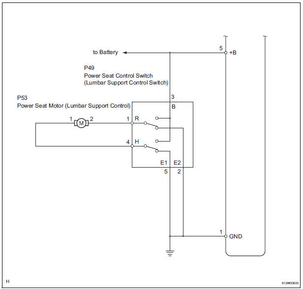
WIRING DIAGRAM
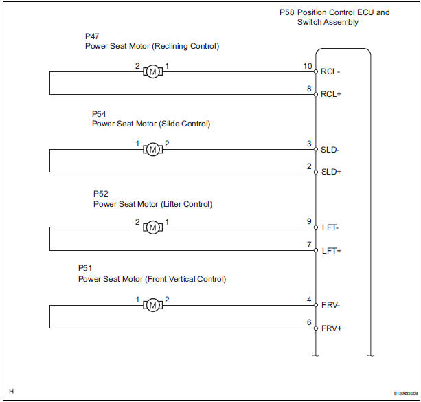
INSPECTION PROCEDURE
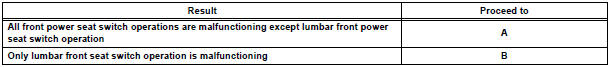
1 CHECK FRONT POWER SEAT OPERATION
- Check that each function of the power seat operates normally by using the front power seat switches.
Result
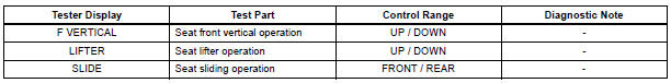
2 READ VALUE OF INTELLIGENT TESTER (FRONT POWER SEAT SWITCH)
- Check the DATA LIST for proper functioning of the front power seat switch.
Position control ECU & switch assembly LH, RH
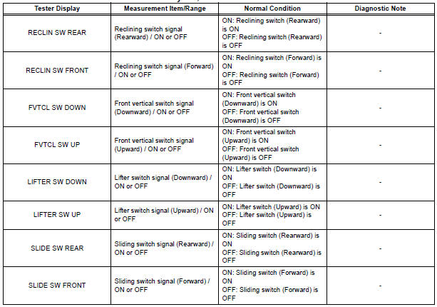
OK: On tester screen, each item changes between ON and OFF according to above chart.
3 PERFORM ACTIVE TEST BY ACTIVE TEST USING INTELLIGENT TESTER (POWER SEAT MOTOR)
- Select the ACTIVE TEST, use the intelligent tester to generate a control command, and then check that the power seat motors operate.
Position control ECU & switch assembly (driver, passenger side)

OK: The power seat motors operate normally.
PROCEED TO NEXT CIRCUIT INSPECTION SHOWN IN PROBLEM SYMPTOMS TABLE
4 INSPECT FRONT SEAT ADJUSTER SUB-ASSEMBLY (POWER SEAT MOTOR)
- Inspect the power seat motor.
OK: The power seat motor operates.
5 CHECK HARNESS AND CONNECTOR (POSITION CONTROL ECU AND SWITCH ASSEMBLY - POWER SEAT MOTOR)
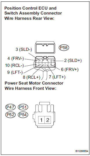
- Disconnect the position control ECU and switch assembly connector and power seat motor connectors.
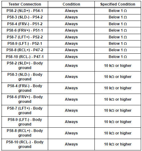
- Measure the resistance according to the value(s) in the table below.
Standard resistance
PROCEED TO NEXT CIRCUIT INSPECTION SHOWN IN PROBLEM SYMPTOMS TABLE
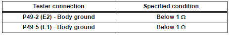
6 CHECK WIRE HARNESS (POWER SEAT CONTROL SWITCH - BATTERY AND BODY GROUND)
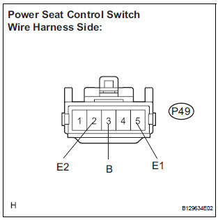
- Disconnect the P49 switch connector.
- Measure the voltage and resistance of the wire harness side connectors.
Standard voltage (Driver side)
Standard resistance (Driver side)
7 INSPECT POWER SEAT CONTROL SWITCH (LUMBER SUPPORT CONTROL)
- Inspect the power seat control switch
8 INSPECT FRONT SEAT ADJUSTER SUB-ASSEMBLY (POWER SEAT MOTOR)
- Inspect the power seat motor.
OK: The power seat motor operates
REPAIR OR REPLACE HARNESS OR CONNECTOR (POWER SEAT CONTROL SWITCH - POWER SEAT MOTOR)
 On-vehicle inspection
1. CHECK POWER SEAT FUNCTION
Check the basic functions.
Operate the power seat switches and check the
following seat functions:
Sliding
Reclining
&nbs ...
 Driving Position Memory Switch Circuit (w/ Memory)
DESCRIPTION
The seat memory switch sends signals to the outer mirror control ECU LH via
the multiplex
communication system to memorize a given seat position. This memory system does
not use a po ...
Other materials:
Window defogger switch
INSPECTION
1. INSPECT WINDOW DEFOGGER SWITCH
Check the defogger switch illuminates.
Standard
If the result is not as specified, replace the switch
assembly or bulb.
Check the defogger timer.
Connect the positive (+) lead from the battery
to terminal 2 and ...
Removal
1. REMOVE BATTERY
2. REMOVE AIR CLEANER ASSEMBLY
HINT:
(See page EM-26)
3. REMOVE SPEED SENSOR (NT SENSOR)
(a) Disconnect the speed sensor connector.
(b) Remove the bolt and speed sensor.
4. REMOVE SPEED SENSOR (NC SENSOR)
(a) Disconnect the speed sensor connector.
(b) Remove th ...
Disassembly
1. REMOVE COOLER THERMISTOR NO.1 (for Automatic Air Conditioning System)
(a) Disengage the 2 claw fittings and the clamp and
remove the cooler thermistor No. 1.
2. REMOVE COOLING UNIT MOTOR SUB-ASSEMBLY WITH FAN
(a) Remove the 3 screws and the cooling unit motor
sub-assembly w/ fan.
3. ...
