Toyota Sienna Service Manual: Precaution
NOTICE: Because the compressor operates at high voltages, wear electric insulated gloves and pull out the service plug to cut the high-voltage circuit before inspection.
1. DO NOT HANDLE REFRIGERANT IN AN ENCLOSED AREA OR NEAR AN OPEN FLAME
2. ALWAYS WEAR EYE PROTECTION
3. BE CAREFUL NOT TO GET LIQUID REFRIGERANT IN YOUR EYES OR ON YOUR SKIN
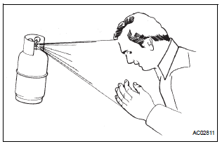
If liquid refrigerant gets in your eyes or on your skin:
(a) Wash the area with lots of cold water.
| CAUTION: Do not rub your eyes or skin. |
(b) Apply clean petroleum jelly to the skin.
(c) Go immediately to a hospital or see a physician for professional treatment.
4. NEVER HEAT CONTAINER OR EXPOSE IT TO OPEN FLAME
5. BE CAREFUL NOT TO DROP CONTAINER OR APPLY PHYSICAL SHOCKS TO IT
6. DO NOT OPERATE COMPRESSOR WITHOUT ENOUGH REFRIGERANT IN REFRIGERANT SYSTEM
If there is not enough refrigerant in the A/C system, oil lubrication will be insufficient and the compressor may be damaged.
Necessary care should be taken to avoid this.
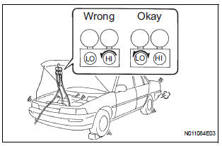
7. DO NOT OPEN HIGH PRESSURE MANIFOLD VALVE WHILE COMPRESSOR IS OPERATING
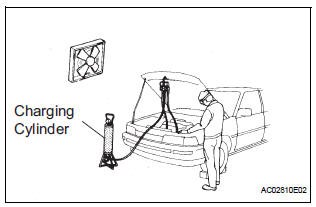
Open and close only the low pressure valve. If the high pressure values are opened, refrigerant flows in the reverse direction causing the charging cylinder to rupture.
If the high pressure valve is opened, refrigerant flows in the reverse direction causing the charging cylinder to rupture.
8. BE CAREFUL NOT TO OVERCHARGE SYSTEM WITH REFRIGERANT
If refrigerant is overcharged, it causes problems such as insufficient cooling, poor fuel economy, engine overheating, etc.
9. SUPPLEMENTAL RESTRAINT SYSTEM (SRS)
(a) This vehicle is equipped with an SRS (Supplemental Restraint System) such as the driver, front passenger, side, curtain shield air bags etc..
Failure to carry out service operation in the correct sequence could cause the SRS to unexpectedly deploy during servicing, possibly leading to a serious accident. Before servicing (including removal or installation of parts, inspection or replacement), be sure to read the precautionary notices on (See page RS-1).
10. GENERAL PRECAUTION
(a) While using the battery during inspection, do not bring the positive and negative tester probes too close to each other as a short circuit may occur.

 Parts location
...
Other materials:
Cruise Control Switch Circuit
DESCRIPTION
The cruise control main switch operates 8 functions: SET, - (COAST),
TAP-DOWN, RES (RESUME), +
(ACCEL), TAP-UP, CANCEL, and MODE. The SET, TAP-DOWN, and - (COAST) functions,
and the RES
(RESUME), TAP-UP, and + (ACCEL) functions are operated with the same switch. The
cruise contr ...
Steering Angle Sensor Communication Stop Mode
DESCRIPTION
Detection Item
Symptom
Trouble Area
Steering Angle Sensor
Communication Stop
Mode
"Steering angle sensor" is not displayed on the
"Communication Bus Check" screen of the
intelligent tester
Applies to &qu ...
Diagnostic trouble code chart
1. DTC CHECK
If a malfunction code is displayed during the DTC check ,
check the suspected area listed for that code in the table
below, and proceed to the appropriate page.
DIAGNOSTIC TROUBLE CODE CHART
DTC No.
Detection Item
Suspect Area
B1244
Light Se ...
