Toyota Sienna Service Manual: Rear Airbag Sensor RH Circuit Malfunction
DTC B1154/38 Rear Airbag Sensor RH Circuit Malfunction
DESCRIPTION
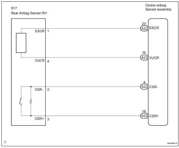
The rear airbag sensor RH circuit consists of the center airbag sensor assembly and rear airbag sensor RH.
If the center airbag sensor assembly receives signals from the rear airbag sensor RH, it judges whether or not the SRS should be activated.
DTC B1154/38 is recorded when a malfunction is detected in the rear airbag sensor RH circuit.
|
DTC No. |
DTC Detecting Condition |
Trouble Area |
|
B1154/38 |
|
|
WIRING DIAGRAM
INSPECTION PROCEDURE
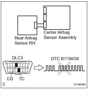
1 CHECK DTC
- Turn the ignition switch to the ON position, and wait for at least 60 seconds.
- Clear the DTCs stored in memory (5).
- Turn the ignition switch to the LOCK position.
- Turn the ignition switch to the ON position, and wait for at least 60 seconds.
- Check the DTCs (5).
OK: DTC B1154/38 is not output. HINT: Codes other than code B1154/38 may be output at this time, but they are not related to this check.
 Go to step 2

USE SIMULATION METHOD TO CHECK
2 CHECK CONNECTION OF CONNECTORS
- Turn the ignition switch to the LOCK position.
- Disconnect the negative (-) terminal cable from the battery, and wait for at least 90 seconds.
- Check that the connectors are properly connected to the center airbag sensor assembly and the rear airbag sensor RH.
OK: The connectors are connected.
CONNECT CONNECTORS

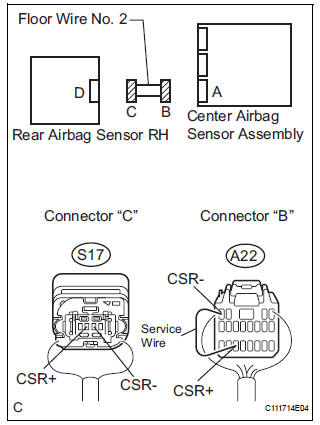
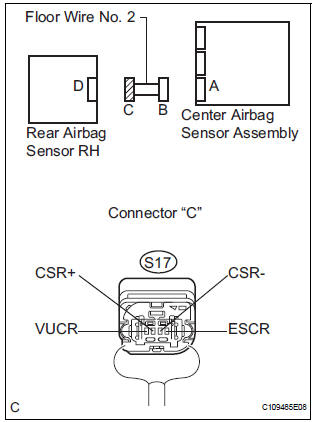
3 CHECK FLOOR WIRE NO. 2 (OPEN)
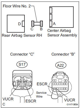
- Disconnect the connectors from the center airbag sensor assembly and the rear airbag sensor RH.
- Using a service wire, connect A22-19 (VUCR) and A22-
20 (ESCR) of connector "B".
NOTICE: Do not forcibly insert a service wire into the terminals of the connector when connecting.
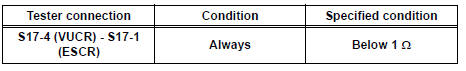
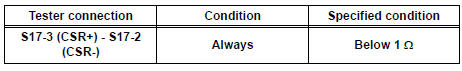
- Measure the resistance according to the value(s) in the table below.
Standard resistance
- Using a service wire, connect A22-18 (CSR+) and A22-4
(CSR-) of connector "B".
NOTICE: Do not forcibly insert a service wire into the terminals of the connector when connecting.
- Measure the resistance according to the value(s) in the table below.
Standard resistance
 REPAIR OR REPLACE FLOOR WIRE
NO. 2
REPAIR OR REPLACE FLOOR WIRE
NO. 2

4 CHECK FLOOR WIRE NO. 2 (SHORT TO B+)
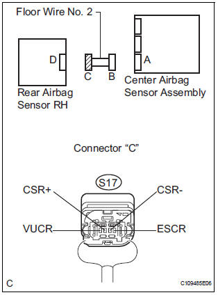
- Disconnect the service wire from connector "B".
- Connect the negative (-) terminal cable to the battery, and wait for at least 2 seconds.
- Turn the ignition switch to the ON position.
- Measure the voltage according to the value(s) in the table below.
Standard voltage

 REPAIR OR REPLACE FLOOR WIRE
NO. 2
REPAIR OR REPLACE FLOOR WIRE
NO. 2

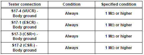
5 CHECK FLOOR WIRE NO. 2 (SHORT TO GROUND)
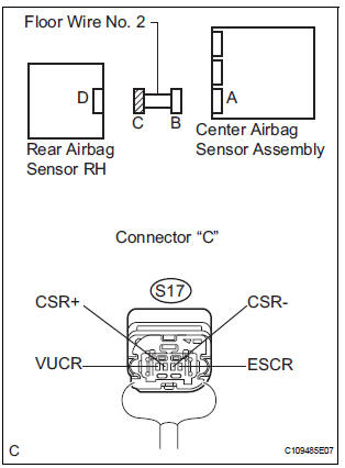
- Turn the ignition switch to the LOCK position.
- Disconnect the negative (-) terminal cable from the battery, and wait for at least 90 seconds.
- Measure the resistance according to the value(s) in the table below.
Standard resistance
 REPAIR OR REPLACE FLOOR WIRE
NO. 2
REPAIR OR REPLACE FLOOR WIRE
NO. 2

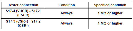
6 CHECK FLOOR WIRE NO. 2 (SHORT)
- Measure the resistance according to the value(s) in the table below.
Standard resistance
 REPAIR OR REPLACE FLOOR WIRE
NO. 2
REPAIR OR REPLACE FLOOR WIRE
NO. 2

7 CHECK REAR AIRBAG SENSOR RH
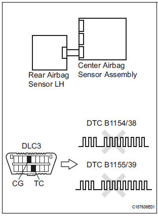
- Connect the connector to the center airbag sensor assembly.
- Interchange the rear airbag sensor LH with RH and connect the connectors to them.
- Connect the negative (-) terminal cable to the battery, and wait for at least 2 seconds.
- Turn the ignition switch to the ON position, and wait for at least 60 seconds.
- Clear the DTCs stored in memory (5).
- Turn the ignition switch to the LOCK position.
- Turn the ignition switch to the ON position, and wait for at least 60 seconds.
- Check the DTCs (5).
Result
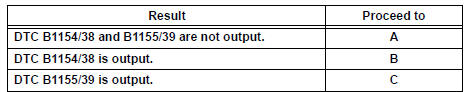
HINT: Codes other than DTC B1154/38 and B1155/39 may be output at this time, but they are not related to this check.
 REPLACE CENTER AIRBAG SENSOR
ASSEMBLY
REPLACE CENTER AIRBAG SENSOR
ASSEMBLY
 REPLACE REAR AIRBAG SENSOR RH

USE SIMULATION METHOD TO CHECK
 Seat Position Airbag Sensor Circuit Malfunction
DTC B1153/25 Seat Position Airbag Sensor Circuit Malfunction
DESCRIPTION
The seat position airbag sensor circuit consists of the center airbag sensor
assembly and the seat
position airbag sensor. ...
 Rear Airbag Sensor LH Circuit Malfunction
DTC B1155/39 Rear Airbag Sensor LH Circuit Malfunction
DESCRIPTION
The rear airbag sensor LH circuit consists of the center airbag sensor
assembly and rear airbag sensor
LH.
If the center airb ...
Other materials:
The Blind Spot Monitor function detection areas
The areas that vehicles can be detected in are outlined below.
The range of the detection area
extends to:
Approximately 11.5 ft. (3.5 m)
from the side of the vehicle
The first 1.6 ft. (0.5 m) from the
side of the vehicle is not in the
detection area
Approximately 9.8 ft. (3 m) ...
Removal
1. REMOVE FRONT DOOR LOWER FRAME BRACKET GARNISH LH
2. REMOVE FRONT DOOR INSIDE HANDLE BEZEL PLUG LH
3. REMOVE POWER WINDOW REGULATOR MASTER SWITCH ASSEMBLY
4. REMOVE FRONT DOOR TRIM BOARD SUBASSEMBLY LH
5. REMOVE SEAT MEMORY SWITCH
Disengage the 4 claws and remove the seat
memor ...
Problem symptoms table
HINT:
Use the table below to help determine the cause of the
problem symptom. The potential causes of the symptoms
are listed in order of probability in the "Suspect Area"
column of the table. Check each symptom by checking the
suspected areas in the order they are listed ...
