Toyota Sienna Service Manual: Rear axle hub bolt
COMPONENTS
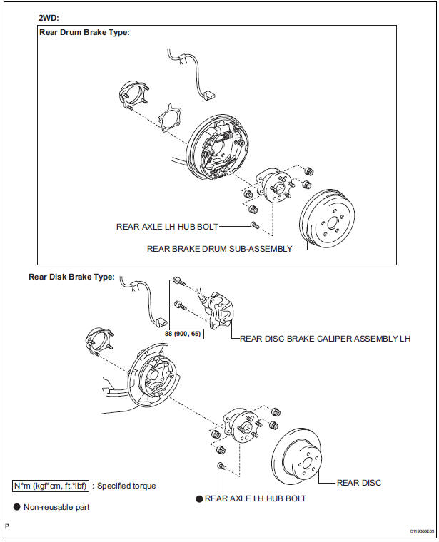
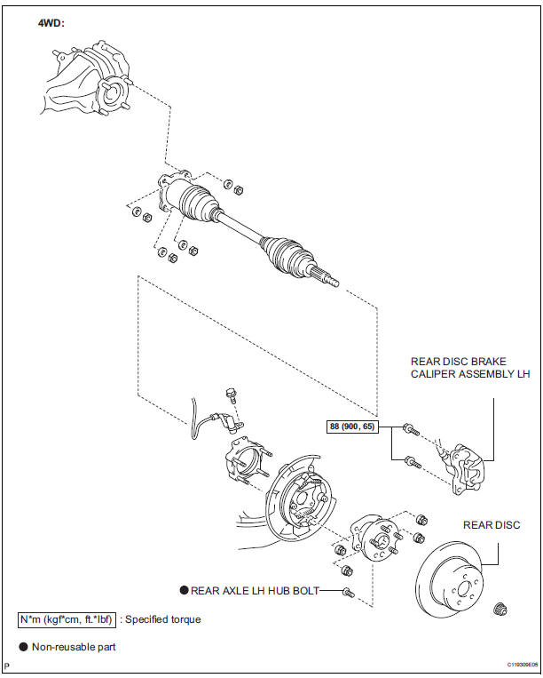
Replacement
HINT: Replace the RH side using the same procedures as for the LH side.
1. REMOVE REAR WHEEL
2. SEPARATE REAR DISC BRAKE CALIPER ASSEMBLY LH
(a) Separate rear disc brake caliper assembly LH for 2WD and disk rear brake type (See page AH-16).
3. SEPARATE REAR DISC BRAKE CALIPER ASSEMBLY LH
(a) Separate rear disc brake caliper assembly LH for 4WD and disk rear brake type (See page AH-19).
4. REMOVE REAR DISC
(a) Remove rear disc for disk rear brake type.
5. REMOVE REAR BRAKE DRUM SUB-ASSEMBLY
(a) Remove rear brake drum sub-assembly for drum rear brake type.
6. REMOVE REAR AXLE LH HUB BOLT
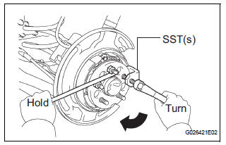
(a) Temporarily install the 2 nuts and washers to the rear axle LH hub bolt as shown in the illustration.
(b) Using SST(s) and a hammer handle or an equivalent to hold the hub & bearing assembly, remove the rear axle LH hub bolt.
SST 09628-10011
7. INSTALL REAR AXLE LH HUB BOLT
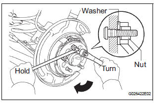
(a) Install a washer and nut to a new bolt, as shown in the illustration.
(b) Using a hammer handle or an equivalent to hold the hub & bearing assembly, install the rear axle LH hub bolt by tightening the nut.
8. INSTALL REAR DISC
(a) Install rear disc for disk rear brake type.
9. INSTALL REAR DISC BRAKE CALIPER ASSEMBLY LH
(a) Install rear disc brake caliper assembly LH for 2WD and disk rear brake type (See page AH-17).
10. INSTALL REAR DISC BRAKE CALIPER ASSEMBLY LH
(a) Install rear disc brake caliper assembly LH for 4WD and disk rear brake type (See page AH-20).
11. INSTALL REAR BRAKE DRUM SUB-ASSEMBLY
(a) Install rear brake drum sub-assembly for drum rear brake type.
12. INSTALL REAR WHEEL Torque: 103 N*m (1,050 kgf*cm, 76 ft.*lbf)
 Installation
1. INSTALL FRONT AXLE ASSEMBLY LH
(a) Install the 2 bolts, nuts and front axle assembly LH
with the 2 bolts and nuts to the shock absorber
assembly front LH.
Torque: 230 N*m (2,350 kgf*cm, 170 ...
 Rear axle hub and bearing (for 2wd)
COMPONENTS
...
Other materials:
Installation
1. INSTALL THROTTLE BODY
Install a new throttle body gasket to the intake air
surge tank.
Install the throttle body with the 4 bolts.
Torque: 10 N*m (102 kgf*cm, 7 ft.*lbf)
Connect the 2 water by-pass hoses.
Connect the throttle body connector and clamp.
2. ...
On-vehicle inspection
1. INSPECT FRONT AXLE HUB BEARING BACKLASH
(a) Using a dial gauge, check for backlash near the
center of the axle hub.
Maximum:
0.05 mm (0.0020 in.)
If backlash exceeds the maximum, replace the
bearing.
NOTICE:
Ensure that the dial gauge is set at right angles
to the measurement surface ...
Сamshaft timing oil control valve assembly
COMPONENTS
ON-VEHICLE INSPECTION
1. INSPECT CAMSHAFT TIMING CONTROL VALVE ASSEMBLY
(a) Connect the intelligent tester to the DLC3.
(b) Turn the ignition switch to the ON position.
(c) Start the engine and warm it up.
(d) Select the intelligent tester from the ACTIVE TEST
...
