Toyota Sienna Service Manual: Removal
HINT: Remove the RH by the same procedure as the LH side.
1. REMOVE REAR WHEEL
2. SEPARATE SKID CONTROL SENSOR WIRE
(a) Disconnect the connector from the skid control sensor.
3. REMOVE REAR BRAKE DRUM SUB-ASSEMBLY (for Drum Type)
(a) Place matchmarks on the rear brake drum subassembly and the axle hub.
(b) Remove the rear brake drum sub-assembly.
4. REMOVE REAR DISC BRAKE CALIPER ASSEMBLY LH (for Disc Type)
(a) Remove the 2 bolts and rear brake caliper assembly LH.
5. REMOVE REAR DISC (for Disc Type)
(a) Place matchmarks on the rear disc and the axle hub.
(b) Remove the rear disc.
6. REMOVE REAR AXLE HUB & BEARING ASSEMBLY LH (See page AH-16)
7. REMOVE REAR SPEED SENSOR
(a) Mount the rear axle hub in a soft jaw vise.
NOTICE: Replace the axle hub assembly if it is dropped or a strong shock is given to it.
(b) Using a pin punch and hammer, drive out the 2 pins and remove the 2 attachments from SST.
(c) Using SST and 2 bolts (Diameter: 12 mm, pitch: 1.5 mm), remove the skid control sensor from the rear axle hub.
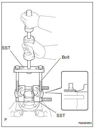
SST 09520-00031 (09520-00040), 09521-00020, 09950-00020
NOTICE:
- If a damage is inflicted to the sensor rotor is damaged, replace the axle hub assembly.
- Do not scratch the contacting surface of the axle hub and speed sensor.
 Rear speed sensor (for 2wd)
Components
...
 Inspection
1. INSPECT REAR SPEED SENSOR
(a) Disconnect the skid control sensor connector.
(b) Measure the resistance between terminals 1 and 2
of the skid control sensor connector.
OK:
Resistance:
le ...
Other materials:
Listening to a
USB memory device
Connecting a USB memory device enables you to enjoy music
from the vehicle speakers.
Touch “USB” on the audio source selection screen.
Connecting a USB memory device
Audio control screen
Pressing the “AUDIO” button displays the audio control screen from
any screens of the selected so ...
Open in Driver Side Squib Circuit
DTC B0101/14 Open in Driver Side Squib Circuit
DESCRIPTION
The driver side squib circuit consists of the center airbag sensor assembly,
the spiral cable and the
steering pad.
The circuit instructs the SRS to deploy when deployment conditions are met.
DTC B0101/14 is recorded when an open ...
Installation
1. INSTALL THROTTLE BODY
(a) Install a new throttle body gasket to the intake air
surge tank.
(b) Install the throttle body with the 4 bolts.
Torque: 10 N*m (102 kgf*cm, 7 ft.*lbf)
(c) Connect the 2 water by-pass hoses.
(d) Connect the throttle body connector and clamp.
2. INSTA ...
