Toyota Sienna Service Manual: Removal
1. RECOVER REFRIGERANT FROM REFRIGERATION SYSTEM (See page AC-172)
2. REMOVE FRONT WHEEL RH
3. REMOVE FRONT FENDER APRON SEAL RH (See page EM-26)
4. REMOVE V-RIBBED BELT (See page EM-6)
5. REMOVE RADIATOR AND FAN ASSEMBLY (See page CO-28)
6. DISCONNECT DISCHARGE HOSE SUB-ASSEMBLY

(a) Remove the bolt and disconnect the discharge hose sub-assembly from the compressor and magnetic clutch.
(b) Remove the O-ring from the discharge hose subassembly.
NOTICE: Seal the openings of the disconnected parts using vinyl tape to prevent entry of moisture and foreign matter.
7. DISCONNECT SUCTION HOSE SUB-ASSEMBLY

(a) Remove the bolt and disconnect the suction hose sub-assembly from the compressor and magnetic clutch.
(b) Remove the O-ring from the suction hose subassembly.
NOTICE: Seal the openings of the disconnected parts using vinyl tape to prevent entry of moisture and foreign matter.
8. REMOVE COMPRESSOR AND MAGNETIC CLUTCH
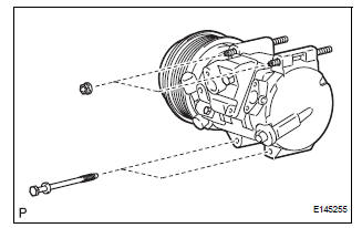
(a) Disconnect the connector.
(b) Release the 2 clamps and wire harness.
(c) Remove the 2 bolts and 2 nuts.
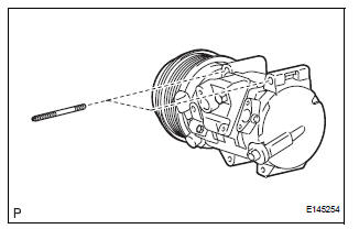
(d) Using a "TORX" socket wrench (E8), remove the 2 stud bolts and the compressor and magnetic clutch.
 Compressor and magnetic clutch
COMPONENTS
...
 Disassembly
1. REMOVE MAGNETIC CLUTCH ASSEMBLY
(a) Place the compressor and magnetic clutch in a vise.
(b) Using locking pliers, hold the magnetic clutch hub.
(c) Remove the bolt, magnetic clutch hub, and
...
Other materials:
System description
1. Radio and navigation assembly outline
Conventionally, 2 separate devices, a "radio and
display" and a "navigation ECU" are used. This
model has adopted a new type, combining these
devices into a single unit.
2. Navigation system outline
Vehicle ...
Terminals of ECU
1. JUNCTION CONNECTOR
Junction connector
with VSC
HINT:
*1: with Dynamic laser cruise control
without VSC
CAN junction connector (with VSC)
with VSC
The connection diagram of the components which
are connected to the CAN junction connector.
2. DLC3
...
Installation
1. INSTALL TIMING CHAIN CASE OIL SEAL
(a) Using SST, tap in a new oil seal until its surface is
flush with the timing chain case edge.
SST 09223-22010, 09506-35010
NOTICE:
Keep the lip free from foreign matter.
Do not tap on the oil seal at an angle.
Make sure that the oil ...
