Toyota Sienna Service Manual: Removal
1. REMOVE WINDSHIELD WIPER MOTOR ASSEMBLY
2. REMOVE FRONT OUTER COWL TOP PANEL SUBASSEMBLY
3. DRAIN ENGINE COOLANT
4. REMOVE V-BANK COVER SUB-ASSEMBLY
5. REMOVE NO. 2 AIR CLEANER INLET
6. REMOVE NO. 1 AIR CLEANER INLET
7. REMOVE AIR CLEANER CAP SUB-ASSEMBLY
8. REMOVE AIR CLEANER CASE SUB-ASSEMBLY
9. REMOVE INTAKE AIR SURGE TANK ASSEMBLY
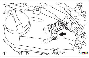
10. REMOVE VVT SENSOR (for Bank 1 Intake Side)
- Disconnect the VVT sensor connector.
- Remove the bolt and VVT sensor.
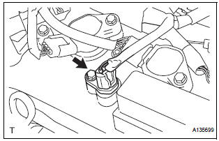
11. REMOVE VVT SENSOR (for Bank 1 Exhaust Side)
- Disconnect the VVT sensor connector.
- Remove the bolt and VVT sensor.
12. REMOVE VVT SENSOR (for Bank 2 Intake Side)
- Disconnect the VVT sensor connector.
- Remove the bolt and VVT sensor.
13. REMOVE VVT SENSOR (for Bank 2 Exhaust Side)
- Disconnect the VVT sensor connector.
- Remove the bolt and VVT sensor.
 On-vehicle inspection
1. CHECK VVT SENSOR OUTPUT VOLTAGE
Turn the ignition switch to the ON position.
Check the voltage between the specified terminal
and body ground.
Standard voltage
While turning ...
 Installation
1. INSTALL VVT SENSOR (for Bank 2 Exhaust Side)
Install the VVT sensor with the bolt.
Torque: 10 N*m (102 kgf*cm, 7 ft.*lbf)
Connect the VVT sensor connector.
2. INSTALL VVT ...
Other materials:
Disassembly
1. INSPECT PACK CLEARANCE OF REVERSE CLUTCH
HINT:
(See page AX-249)
2. INSPECT PACK CLEARANCE OF DIRECT CLUTCH
AND OVERDRIVE CLUTCH
HINT:
(See page AX-249)
3. REMOVE DIRECT MULTIPLE DISC CLUTCH DISC
(a) Using a screwdriver, remove the snap ring from the
intermediate shaft.
(b) Remo ...
Heated steering
wheel/seat heaters
Heated steering wheel and seat heaters heat the side grips of the
steering wheel and seats, respectively.
WARNING
Care should be taken to prevent injury if anyone in the
following categories
comes in contact with the steering wheel and seats when the heater
is on:
...
Cellular Phone Registration Failure, Phone Directory Transfer Failure
INSPECTION PROCEDURE
1 CHECK CURRENT CONDITIONS
Proceed to the next step according to the table below.
RESULT
2 CHECK USING ANOTHER CELLULAR PHONE
Check if the system functions using another Bluetooth
compatible cellular phone.
HINT:
Confirm that either the same or a di ...
