Toyota Sienna Service Manual: Removal
1. REMOVE ENGINE ASSEMBLY WITH TRANSAXLE
HINT: See page EM-26
2. REMOVE OIL LEVEL GAUGE GUIDE SUBASSEMBLY (See page EM-39) 3. REMOVE NO. 1 OIL PIPE (See page EM-77) 4. REMOVE OIL PIPE (See page EM-77) 5. REMOVE CRANKSHAFT PULLEY (See page EM-79) 6. SEPARATE OIL COOLER PIPE
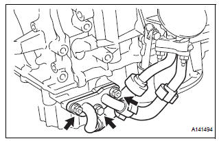
(a) Remove the bolt and 2 nuts, and disconnect the oil cooler pipe from the oil pan sub-assembly.
(b) Remove the gasket from the oil pan sub-assembly.
7. REMOVE WATER INLET HOUSING (See page CO-12) 8. REMOVE CYLINDER HEAD COVER SUB-ASSEMBLY (for Bank 1) (See page EM-82) 9. REMOVE CYLINDER HEAD COVER SUB-ASSEMBLY (for Bank 2) (See page EM-82) 10. REMOVE NO. 2 OIL PAN SUB-ASSEMBLY (See page EM-82) 11. REMOVE OIL STRAINER SUB-ASSEMBLY (See page EM-83) 12. REMOVE OIL PAN SUB-ASSEMBLY (See page EM- 83) 13. REMOVE TIMING CHAIN COVER SUB-ASSEMBLY
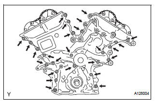
(a) Remove the 23 bolts and 2 nuts as shown in the illustration.
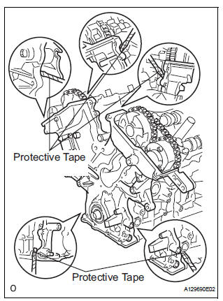
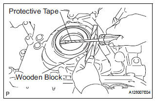
(b) Remove the timing chain cover by prying between the timing chain cover and cylinder head or cylinder block with a screwdriver.
| NOTICE: Be careful not to damage the contact surfaces of the cylinder head, cylinder block and chain cover. |
HINT: Tape the screwdriver tip before use.
(c) Remove the gasket.
14. REMOVE TIMING CHAIN CASE OIL SEAL
(a) Using a screwdriver, pry out the oil seal.
HINT: Tape the screwdriver tip before use.
 Oil pump
Components
...
 Disassembly
1. REMOVE OIL PUMP RELIEF VALVE
(A) using a 27 mm socket wrench, remove the relief
valve plug.
(B) remove the valve spring and oil pump relief valve.
2. REMOVE OIL PUMP COVER
(a) Remove ...
Other materials:
Improper Aiming of Radar Sensor Beam Axis
DTC P1572 Improper Aiming of Radar Sensor Beam Axis
DESCRIPTION
This DTC is output when the scanning angle of the laser sensor is incorrect.
This DTC is also output when
the laser sensor beam axis is determined to be in an incorrect position.
DTC No.
DTC Detection Condition
...
On-vehicle inspection
1. CONNECT INTELLIGENT TESTER
(a) Connect the intelligent tester to the DLC3.
(b) Start the engine and run at idle.
(c) Select the ACTIVE TEST mode on the intelligent
tester.
HINT:
Please refer to the intelligent tester operator's
manual for further details.
2. INSPECT ACTUATOR MOTOR ...
Installation
1. INSTALL TIRE PRESSURE WARNING ECU
(a) Connect the connector to the tire pressure warning
ECU.
(b) Install the tire pressure warning ECU with the screw.
2. INSTALL INSTRUMENT PANEL SAFETY PAD SUBASSEMBLY
HINT:
Refer to the instructions for INSTALLATION of the
instrument panel safety ...
