Toyota Sienna Service Manual: Removal
1. DISCONNECT BATTERY NEGATIVE TERMINAL 2. REMOVE FRONT DOOR SCUFF PLATE LH HINT: (See page IP-6) 3. REMOVE FRONT DOOR SCUFF PLATE RH HINT: (See page IP-6) 4. REMOVE COWL SIDE TRIM BOARD LH HINT: (See page IP-6) 5. REMOVE COWL SIDE TRIM BOARD RH HINT: (See page IP-6) 6. REMOVE INSTRUMENT PANEL FINISH PANEL SUBASSEMBLY LOWER LH HINT: (See page IP-6) 7. REMOVE GLOVE COMPARTMENT DOOR STOPPER SUB-ASSEMBLY HINT: (See page IP-7) 8. REMOVE GLOVE COMPARTMENT DOOR ASSEMBLY HINT: (See page IP-7) 9. REMOVE FLOOR CARPET COVER CENTER LH HINT: (See page IP-8) 10. REMOVE FLOOR CARPET COVER CENTER RH HINT: (See page IP-8) 11. REMOVE INSTRUMENT CLUSTER FINISH PANEL CENTER NO.1 HINT: (See page IP-8) 12. REMOVE INSTRUMENT CLUSTER FINISH PANEL CENTER NO.2 HINT: (See page IP-8)
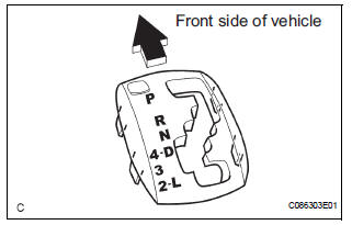
13. REMOVE SHIFT LEVER KNOB SUB-ASSEMBLY
(a) Remove the floor shift lever knob sub-assembly.
14. REMOVE POSITION INDICATOR HOUSING ASSEMBLY
(a) Using a screwdriver, remove the position indicator housing assembly from the instrument cluster finish panel assembly center.
15. REMOVE INSTRUMENT CLUSTER FINISH PANEL ASSEMBLY CENTER
HINT: (See page IP-9)
16. REMOVE SHIFT LEVER CAP
(a) Using a small screwdriver, remove the shift lever cap from the position indicator housing assembly.
17. REMOVE INSTRUMENT CLUSTER FINISH PANEL SUB-ASSEMBLY LOWER CENTER
HINT: (See page IP-9)
18. DISCONNECT TRANSMISSION CONTROL CABLE ASSEMBLY
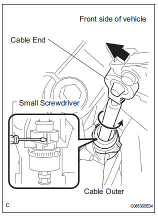
(a) Using a screwdriver, disconnect the cable end from the shift lever assembly.
(b) Using a small screwdriver, disconnect the outer of transmission control cable assembly from the shift lever assembly.
19. REMOVE SHIFT LEVER ASSEMBLY
(a) Disconnect the 2 connectors.
(b) Remove the 4 bolts and disconnect the shift lever assembly from the vehicle.
 Shift lever
Components
...
 Disassembly
1. REMOVE INDICATOR LIGHT WIRE SUB-ASSEMBLY
(a) Remove the indicator light wire sub assembly from
the position indicator light guide.
2. REMOVE POSITION INDICATOR LIGHT BULB
(a) Remove the shi ...
Other materials:
Rear Clearance Sonar Sensor LH Circuit
DESCRIPTION
An ultrasonic sensor consists of a sensor portion that transmits and receives
ultrasonic waves and a preamplifier
that amplifies them. The ultrasonic sensor outputs the ultrasonic waves and
sends the received
signals to the clearance warning ECU.
WIRING DIAGRAM
INSPECTION PR ...
Reassembly
1. INSTALL MAGNETIC CLUTCH ASSEMBLY
(a) Install the magnetic clutch stator while aligning the
protrusion on the stator with the notch on the air
compressor assembly as shown in the illustration.
(b) Using a snap ring expander, install a new snap ring
with the chamfered side facing up.
...
Stowing the spare tire
Lay down the tire with the outer
side (valve stem) facing up, and
install the holding bracket.
Turn the jack handle clockwise
to raise the tire until the tire is in
the correct position as the jack
handle skips.
Stow the tools.
The compact spare tire
The compact s ...
