Toyota Sienna Service Manual: Reassembly
1. INSTALL MAGNETIC CLUTCH ASSEMBLY
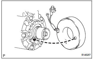
(a) Install the magnetic clutch stator while aligning the protrusion on the stator with the notch on the air compressor assembly as shown in the illustration.
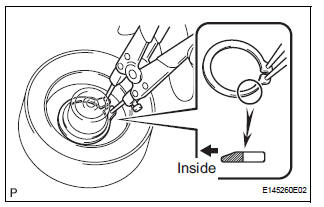
(b) Using a snap ring expander, install a new snap ring with the chamfered side facing up.
NOTICE: Take care not to damage the seal cover of the bearing when installing the snap ring
(c) Install the screw and connect the connector.
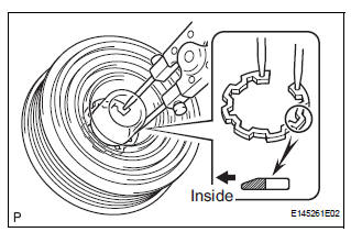
(d) Using a snap ring expander, install the magnetic clutch rotor and a new snap ring with the chamfered side facing up.
NOTICE:
- Do not expand the snap ring by more than 35.5 mm (1.39 in.) when installing it.
- Do not damage the seal cover of the bearing when installing the snap ring.
(e) Install the magnet clutch washer and the magnet clutch hub.
NOTICE: Do not change the combination of the magnetic clutch washers used before disassembly.
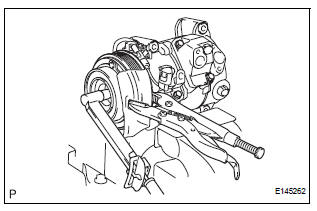
(f) Using vise pliers, hold the magnetic clutch hub and install the bolt.
Torque: 18 N*m (183 kgf*cm, 13 ft.*lbf)
NOTICE: Make sure that there is no foreign matter or oil on the compressor shaft, bolt, and clutch hub.
 Inspection
1. INSPECT MAGNETIC CLUTCH CLEARANCE
(a) Set the dial indicator to the magnetic clutch hub.
(b) Connect the battery positive lead to the terminal 1 of
the magnet clutch connector and the nega ...
 Installation
1. INSTALL COMPRESSOR AND MAGNETIC CLUTCH
(a) Using a "TORX" socket wrench (E8), install the
compressor and magnetic clutch with the 2 stud
bolts.
Torque: 10 N*m (102 kgf*cm, 7.4 ft. ...
Other materials:
Short to GND in Rear Curtain Shield Squib RH
Circuit
DTC B1632/81 Short to GND in Rear Curtain Shield Squib RH
Circuit
DESCRIPTION
The rear curtain shield squib RH circuit consists of the center airbag sensor
assembly and the curtain
shield airbag assembly RH.
The circuit instructs the SRS to deploy when deployment conditions are met.
DTC ...
Inspection
1. INSPECT WINDSHIELD WIPER MOTOR ASSEMBLY
LO Operation Check
Connect the battery (+) to the terminal 1 (+1) of
the connector, the battery (-) to the terminal 5
(E) of the connector, and check that the motor
operates at low speed (LO).
HI Operation Check
...
A/C ECU Communication Stop
DTC B1262 A/C ECU Communication Stop
DESCRIPTION
DTC B1262 is output when communication between the A/C amplifier and the
multiplex network gateway
ECU stops for more than 10 seconds.
DTC No.
DTC Detection Condition
Trouble Area
B1262
A/C ECU communicat ...
