Toyota Sienna 2010-2026 Owners Manual: Air outlets
Location of air outlets
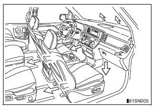
The air outlets and air volume changes according to the selected air flow mode.
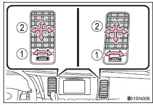
Adjusting the position of and opening and closing the air outlets
- Center outlets
- Right and left side outlets
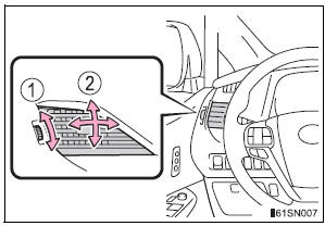
- Turn the knob to open or close the vent.
- Direct air flow to the left or right, up or down.
Using automatic mode
Fan speed is adjusted automatically according to the temperature setting and the ambient conditions.
Therefore, the fan may stop for a while until warm or cool air is ready to flow immediately after the “AUTO” button is pressed.
When the outside temperature exceeds 75°F (24°C) and the air conditioning system is on
- In order to reduce the air conditioning power consumption, the air
conditioning
system may switch to recirculated air mode automatically.
This may also reduce fuel consumption.
- Recirculated air mode is selected as a default mode when the engine switch is turned to the “ON” position (vehicles without a smart key system) or IGNITION ON mode (vehicles with a smart key system).
- It is possible to switch to outside air mode at any time by pressing
 .
.
Fogging up of the windows
- The windows will easily fog up when the humidity in the vehicle is high.
Pressing “A/C” button on will dehumidify the air from the outlets and defog the windshield effectively.
- If you turn “A/C” off, the windows may fog up more easily.
- The windows may fog up if the recirculated air mode is used.
Outside/recirculated air mode
- When driving on dusty roads such as tunnels or in heavy traffic, set

to the recirculated air mode. This is effective in preventing outside air from entering the vehicle interior. During cooling operation, setting the recirculated air mode will also cool the vehicle interior effectively. - Outside/recirculated air mode may automatically switch depending on the temperature setting or the inside temperature.
Temperature display
The temperature display on the multi-information display can be changed.
When  is selected for the air
outlets used
For your driving comfort, air flowing to the feet may be warmer than air flowing to the upper body depending on the temperature setting.
When the outside temperature is low
The dehumidification function may not operate even when the “A/C” button is pressed.
When “A/C ON” flashes in the display
Press the “A/C” button and turn off the air conditioning system before turning it on once more. There may be a problem in the air conditioning system if “A/C ON” continues to flash. Turn the air conditioning system off and have it inspected by your Toyota dealer.
Ventilation and air conditioning odors
- To let fresh air in, set the air conditioning system to the outside air mode.
- During use, various odors from inside and outside the vehicle may enter into and accumulate in the air conditioning system. This may then cause odor to be emitted from the vents.
- To reduce potential odors from occurring:
- It is recommended that the air conditioning system be set to outside air mode prior to turning the vehicle off.
- The start timing of the blower may be delayed for a short period of time immediately after the air conditioning system is started in automatic mode.
Air conditioning filter
Customization
Settings (e.g. “AUTO” button linked operation) can be changed.
| WARNING To prevent the windshield from fogging up
To prevent burns
|
 during
| NOTICE To prevent battery discharge Do not leave the air conditioning system on longer than necessary when the engine is stopped. |
 Other functions
Switching between outside air and recirculated air modes
Press .
The mode switches between outside air mode (
appears on the
display) and recirculated air mode (
appears on the display) each
...
 Rear automatic air
conditioning system
Rear automatic air
conditioning system
Airflow and outlets are automatically adjusted according to the
temperature setting. ...
Other materials:
The Blind Spot Monitor function detection areas
The areas that vehicles can be detected in are outlined below.
The range of the detection area
extends to:
Approximately 11.5 ft. (3.5 m)
from the side of the vehicle
The first 1.6 ft. (0.5 m) from the
side of the vehicle is not in the
detection area
Approximately 9.8 ft. (3 m) ...
PBD Pulse Sensor Malfunction
DTC B2222 PBD Pulse Sensor Malfunction
DESCRIPTION
A pulse sensor is built into the back door for a jam and foreign
object detection and for back door
position detection. The jam and foreign object detection feature of the
pulse sensor monitors the
operating speed of the back door whi ...
Reassembly
1. INSTALL CENTER CLUSTER MODULE KNOB NO.6
(for Automatic Air Conditioning System)
2. INSTALL CENTER CLUSTER MODULE KNOB NO.5
(for Automatic Air Conditioning System)
3. INSTALL CLOCK ORNAMENT
4. INSTALL PRINTED WIRE INTEGRATION BOARD
SUB-ASSEMBLY (for Automatic Air Conditioning
System)
5. IN ...
