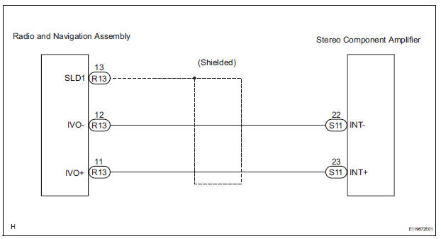
Toyota Sienna Service Manual: Navigation Voice Circuit
DESCRIPTION
This circuit is used when the voice guidance in the navigation system is on.
WIRING DIAGRAM
INSPECTION PROCEDURE
1 CHECK HARNESS AND CONNECTOR (RADIO AND NAVIGATION ASSEMBLY - STEREO COMPONENT AMPLIFIER)
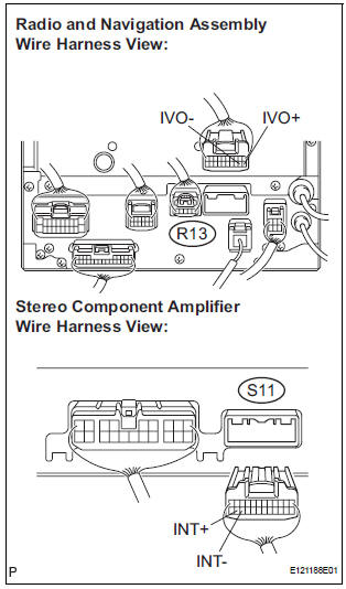
- Disconnect the radio and navigation assembly connector R13 and stereo component amplifier connector S11.
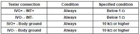
- Measure the resistance according to the value(s) in the table below.
Standard resistance
PROCEED TO NEXT CIRCUIT INSPECTION SHOWN IN PROBLEM SYMPTOMS TABLE
 Reverse Signal Circuit
DESCRIPTION
The radio and navigation assembly receives a reverse signal from the
park/neutral position switch and
information about the GPS antenna, and then adjusts vehicle position.
WIRING DIAG ...
 Display Signal Circuit between Television Display Assembly and Radio
and Navigation Assembly
Display Signal Circuit between Television Display Assembly and Radio
and Navigation Assembly
DESCRIPTION
This circuit sends a DVD image signal from the television display assembly to
the radio and navigation
assembly.
WIRING DIAGRAM
INSPECTION PROCEDURE
1 CHECK HARNESS AND CONNECTO ...
Other materials:
Installation
1. INSTALL FRONT PASSENGER AIRBAG ASSEMBLY
Install the front passenger airbag assembly with the
2 screws.
2. INSTALL INSTRUMENT PANEL SUB-ASSEMBLY
3. CONNECT FRONT PASSENGER AIRBAG ASSEMBLY CONNECTOR
Connect the connector to the front passenger airbag
assembly.
...
Installation
1. INSTALL BLOWER ASSEMBLY
(a) Install the blower assembly.
(b) Install the bolt, the 2 screws and the nut.
Torque: Bolt A
9.8 N*m (100 kgf*cm, 87 in.*lbf)
(c) Install the 2 clamps and 2 nuts and wire harness.
2. INSTALL INSTRUMENT PANEL SUB-ASSEMBLY WITH PASSENGER AIRBAG ASSEMBLY
H ...
Transmission Range Sensor Circuit Malfunction (PRNDL Input)
DESCRIPTION
The park/neutral position switch detects the shift lever position and sends
signals to the ECM.
HINT:
After confirming DTC P0705, use the intelligent tester to confirm the PNP
switch signal in the ALL menu
(to reach the ALL menu: DIAGNOSIS / ENHANCED OBD II / DATA LIST / ...
