Toyota Sienna 2010-2026 Owners Manual: Anti-glare function
- Manual anti-glare inside rear view mirror
Reflected light from the headlights of vehicles behind can be reduced by operating the lever.
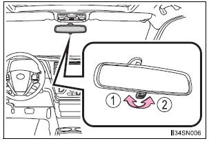
- Normal position
- Anti-glare position
- Auto anti-glare inside rear view mirror
Responding to the level of brightness of the headlights of vehicles behind, the reflected light is automatically reduced.
Changing automatic anti-glare function mode
On/off
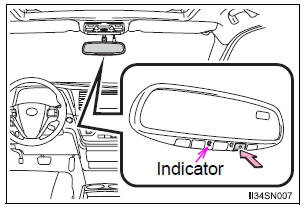
When the automatic anti-glare function is in on mode, the indicator illuminates.
The function will set to on mode each time the engine switch is turned to “ON” position (vehicles without a smart key system) or IGNITION ON mode (vehicles with a smart key system).
Pressing the button turns the function to off mode. (The indicator also turns off.)
To prevent sensor error (vehicles with auto anti-glare inside rear view mirror)
To ensure that the sensors operate properly, do not touch or cover them.
| WARNING
Do not adjust the position of the mirror while driving.
Doing so may lead to mishandling of the vehicle and cause an accident, resulting in death or serious injury. |
 Adjusting the height of rear view mirror
The height of the rear view mirror can be adjusted to suit your driving
posture.
Adjust the height of the rear view
mirror by moving it up and down. ...

Other materials:
Transfer
SERVICE DATA
TORQUE SPECIFICATIONS
PROPELLER SHAFT
SERVICE DATA
TORQUE SPECIFICATIONS
DRIVE SHAFT
SERVICE DATA
TORQUE SPECIFICATIONS
DIFFERENTIAL
SERVICE DATA
TORQUE SPECIFICATIONS
AXLE
SERVICE DATA
TORQUE SPECIFICATIONS
...
Removal
1. DISCONNECT CABLE FROM NEGATIVE BATTERY
TERMINAL
2. REMOVE FRONT DOOR SCUFF PLATE LH
3. REMOVE COWL SIDE TRIM SUB-ASSEMBLY LH
4. REMOVE LOWER INSTRUMENT PANEL FINISH
PANEL SUB-ASSEMBLY LH (See page IP-6)
5. REMOVE TIRE PRESSURE WARNING RESET SWITCH
(a) Disengage the 2 claws and remove t ...
Changing the engine switch positions
“LOCK”
The steering wheel is locked and
the key can be removed. (The key
can be removed only when the
shift lever is in “P”.)
“ACC”
Some electrical components such
as the audio system can be used.
“ON”
All electrical components can be
used.
“START”
...
