Toyota Sienna Service Manual: Vehicle Speed Sensor "A"
DTC P0500 Vehicle Speed Sensor "A"
DESCRIPTION
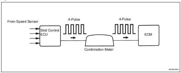
The speed sensor detects the wheel speed and sends the appropriate signals to the skid control ECU.
The skid control ECU converts these wheel speed signals into a 4-pulse signal and outputs it to the ECM via the combination meter. The ECM determines the vehicle speed based on the frequency of these pulse signals.
MONITOR DESCRIPTION
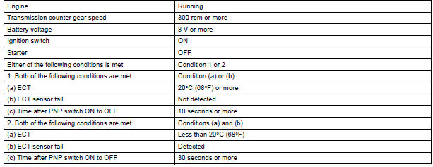
The ECM assumes that the vehicle is being driven when the transmission counter gear indicates more than 300 rpm and over 30 seconds have passed since the park / neutral position switch was turned OFF.
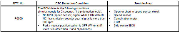
If thre is no signal from the vehicle speed sensor with these conditions satisfied, the ECM concludes that the vehicle speed sensor is malfunctioning. The ECM will turn on the MIL and a DTC will be set.
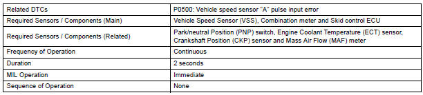
MONITOR STRATEGY
TYPICAL ENABLING CONDITIONS

TYPICAL MALFUNCTION THRESHOLDS

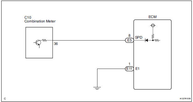
WIRING DIAGRAM
INSPECTION PROCEDURE
HINT: Read freeze frame data using the intelligent tester. The ECM records vehicle and driving condition information as freeze frame data the moment a DTC is stored. When troubleshooting, freeze frame data can be helpful in determining whether the vehicle was running or stopped, whether the engine was warmed up or not, whether the air-fuel ratio was lean or rich, as well as other data recorded at the time of a malfunction.
1 CHECK SPEEDOMETER
- Drive the vehicle and check whether the operation of the speedometer in the combination meter is normal.
HINT:
- The vehicle speed sensor is operating normally if the speedometer reading is normal.
- If the speedometer does not operate, check it by following the procedure described in speedometer malfunction.
2 READ VALUE OF INTELLIGENT TESTER (VEHICLE SPEED)
- Connect the intelligent tester to the DLC3.
- Turn the ignition switch to the ON position.
- Turn the tester on.
- Select the following menu items: DIAGNOSIS / ENHANCED OBD II / DATA LIST / PRIMARY / VEHICLE SPD.
- Drive the vehicle.
- Read the value displayed on the tester.
OK: Vehicle speeds displayed on tester and speedometer display are equal.
3 CHECK COMBINATION METER ASSEMBLY (+S VOLTAGE)
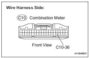
- Disconnect the C10 combination meter connector.
- Turn the ignition switch to the ON position.
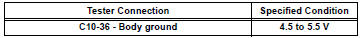
- Measure the voltage between the terminal of the combination meter and body ground.
Standard voltage
- Reconnect the combination meter connector.
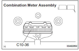
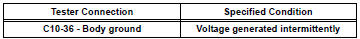
4 CHECK COMBINATION METER ASSEMBLY (SPD SIGNAL WAVEFORM)
- Shift the transmission gear selector lever to the neutral position.
- Jack up the vehicle.
- Turn the ignition switch to the ON position.
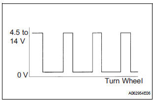
- Measure the voltage between the terminal of the combination meter and body ground while the wheel is turned slowly.
Standard voltage
HINT: The output voltage should fluctuate up and down, similarly to the diagram, when the wheel is turned slowly.
5 CHECK HARNESS AND CONNECTOR (COMBINATION METER ASSEMBLY - ECM)
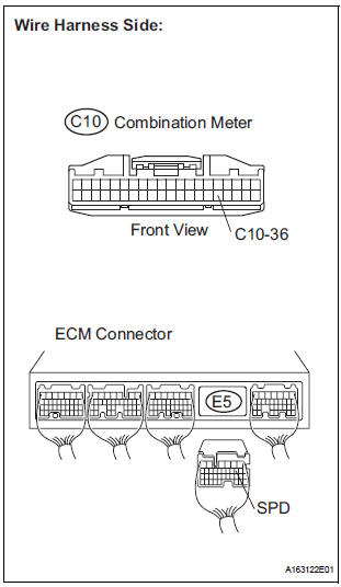
- Disconnect the C10 combination meter connector.
- Disconnect the E5 ECM connector.
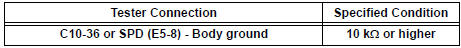
- Measure the resistance.
Standard resistance (Check for open)

Standard resistance (Check for short)
- Reconnect the combination meter connector.
- Reconnect the ECM connector.
REPLACE ECM
 Evaporative Emission Control System Leak
Detected
Evaporative Emission Control System Leak
Detected
DTC P0455 Evaporative Emission Control System Leak
Detected (Gross Leak)
DTC P0456 Evaporative Emission Control System Leak
Detected (Very Small Leak)
DTC SUMMARY
DESCRIPTION
The circuit des ...
 Brake Switch
DTC P0504 Brake Switch "A" / "B" Correlation
DTC P0724 Brake Switch "B" Circuit High
DESCRIPTION
The stop light switch is a duplex system that transmits two signals: S ...
Other materials:
Removal
1. PRECAUTION
CAUTION:
Be sure to read "PRECAUTION" thoroughly before
servicing.
2. DISCONNECT CABLE FROM NEGATIVE BATTERY
TERMINAL
CAUTION:
Wait for 90 seconds after disconnecting the cable to
prevent the airbag working.
3. REMOVE STEERING WHEEL NO.3 COVER LOWER
Using a ...
SPD Signal Error
DTC 58-43 SPD Signal Error
DTC 80-43 SPD Signal Error
DESCRIPTION
DTC No.
DTC Detection Condition
Trouble Area
58-43
A difference between the GPS speed and SPD pulse is
detected.
Speed signal circuit
Radio and navigation assembly
...
How to proceed with troubleshooting
The intelligent tester can be used at steps 3, 7, 10, and 13.
1 VEHICLE BROUGHT TO WORKSHOP
2 CUSTOMER PROBLEM ANALYSIS
(a) Interview the customer to confirm the trouble.
3 DTC CHECK/CLEAR AND FREEZE FRAME DATA
4 PROBLEM SYMPTOM CONFIRMATION
5 PROBLEM SYMPTOM SIMULATION
6 SYMPTOM SI ...
