Toyota Sienna 2010-2026 Owners Manual: Drive information
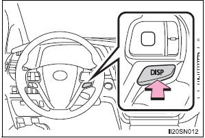
Items displayed can be switched by pressing the “DISP” switch.
- Current fuel economy
Displays the current rate of fuel consumption.
Use the displayed current fuel consumption as a reference.
- Average fuel economy Displays the average fuel consumption since the function was reset respectively.*
Use the displayed average fuel consumption as a reference.
*: Press and hold the “DISP” switch to reset.
- Distance
Displays the estimated maximum distance that can be driven with the quantity of fuel remaining and the distance driven after the function was reset respectively.
- This distance is computed based on your average fuel consumption. As a result, the actual distance that can be driven may differ from that displayed.
- When only a small amount of fuel is added to the tank, the display
may
not be updated.
When refueling, turn the engine switch off. If the vehicle is refueled without turning the engine switch off, the display may not be updated.
- Setting The settings of the following items can be changed, refer to
- Eco Driving Indicator Light
Select to activate/deactivate the Eco Driving Indicator Light.
- Language Select to change the language on the display.
- Units Select to change the units for measure of the fuel consumption and outside temperature.
- Display off
A blank screen is displayed.
Setting display automatic cancelation
In the following situations, setting display in which the settings can be changed through the “DISP” switch will automatically be turned off.
- If a warning message appears while the setting display is displayed
- When the vehicle begins to move while the setting display is displayed
Liquid crystal display
Small spots or light spots may appear on the display. This phenomenon is characteristic of liquid crystal displays, and there is no problem continuing to use the display.
| WARNING The information display at low temperatures Allow the interior of the vehicle to warm up before using the liquid crystal information display. At extremely low temperatures, the display monitor may respond slowly, and display changes may be delayed. For example, there is a lag between the driver’s shifting and the new gear number appearing on the display. This lag could cause the driver to downshift again, causing rapid and excessive engine braking and possibly an accident resulting in death or injury. Cautions during setting up the display As the engine needs to be running during setting up the display, ensure that the vehicle is parked in a place with adequate ventilation. In a closed area such as a garage, exhaust gases including harmful carbon monoxide (CO) may collect and enter the vehicle. This may lead to death or a serious health hazard. |
| NOTICE During setting up the display To prevent battery discharge, ensure that the engine is running while setting up the display features. |
 Display contents
The multi-information display presents the driver with a variety of
driving-related data.
Drive information
Warning messages
...

Other materials:
Back Door Courtesy Switch Circuit
DESCRIPTION
The fold seat control ECU receives signals from the back door courtesy switch
and detects the state of the
back door (open/close). If the ECU does not detect that the back door is open,
the seat stowing and return
functions are not available.
WIRING DIAGRAM
INSPECTION PROCED ...
High Temperature
DTC 44-47 High Temperature
DESCRIPTION
DTC No.
DTC Detection Condition
Trouble Area
44-47
Sensor detects that DVD unit temperature is high (Over
80C).
Television display assembly
INSPECTION PROCEDURE
HINT:
After the inspection is completed, cl ...
Clearance Warning ECU Power Source Circuit
DESCRIPTION
This circuit provides power to the clearance warning ECU.
WIRING DIAGRAM
INSPECTION PROCEDURE
1 CHECK HARNESS AND CONNECTOR (CLEARANCE WARNING ECU - AIR CONDITIONER
AMPLIFIER)
Disconnect the connectors from the clearance warning
ECU C9 and air conditioner amplifier con ...
