Toyota Sienna Service Manual: Initialization
1. ZERO POINT CALIBRATION
NOTICE: Make sure that the front passenger seat is not occupied before performing the operation. HINT: Perform the zero point calibration and sensitivity check if any of the following conditions occur.
- The occupant classification ECU is replaced.
- Accessories (seatback tray and seat cover, etc.) are installed.
- The front passenger seat is removed from the vehicle.
- The passenger airbag ON/OFF indicator ("OFF") comes on when the front passenger seat is not occupied.
- The vehicle is brought to the workshop for repair due to an accident or a collision.
- Zero point calibration and sensitivity check procedures
HINT: Make sure that zero point calibration has finished normally, and then perform the sensitivity check.
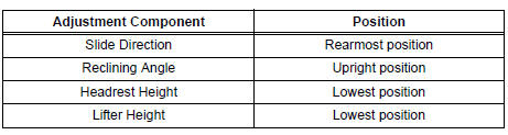
- Adjust the seat position according to the table below.
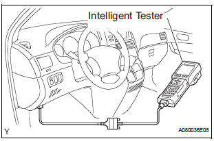
- Connect the intelligent tester to the DLC3.
- Turn the ignition switch to the ON position.
- Perform the zero point calibration by following the prompts on the tester screen.
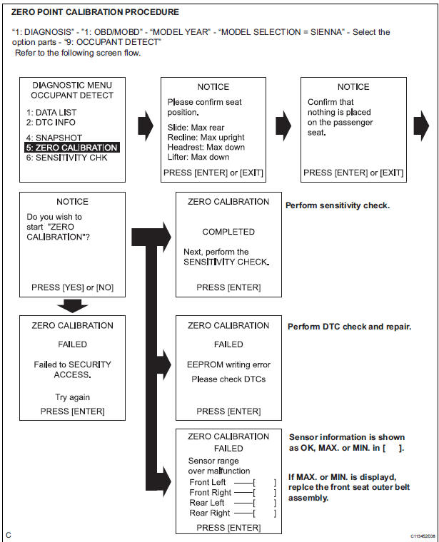
HINT: Refer to the intelligent tester operator's manual for further details
OK: "COMPLETE" is displayed.
- Perform the sensitivity check by following the prompts on the tester screen.
- Confirm that the beginning sensor reading is
within the standard range.
Standard value: -3.2 to 3.2 kg (-7 to 7 lb)
- Place a 30 kg (66.14 lb) weight (eg. a 30 kg (66.14 lb) of lead mass) onto the front passenger seat.
- Confirm that the sensitivity is within the standard range.
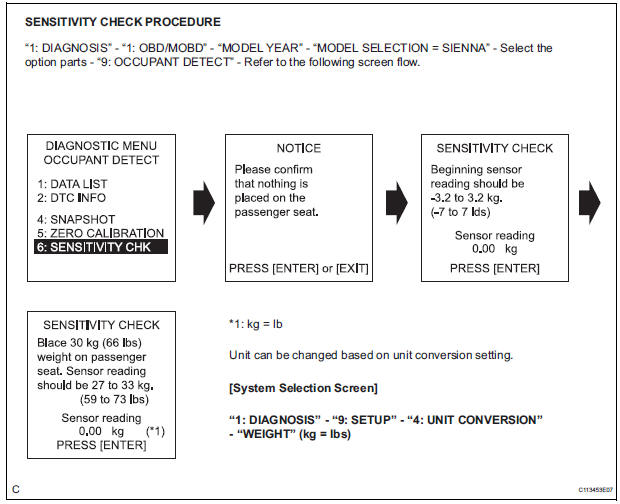
Standard value: 27 to 33 kg (59.52 to 72.75 lb)
HINT:
- When performing the sensitivity check, use a solid metal weight (the check result may not appear properly if a liquid weight is used).
- If the sensitivity deviates from the standard range, retighten the bolts of the front passenger seat taking care not to deform the seat rail. After performing this procedure, if the sensitivity is not within the standard range, replace the front seat assembly RH.
- If zero point calibration has not finished normally, replace the front seat assembly RH.
Problem symptoms table
HINT: Proceed to the troubleshooting for each circuit in the table below.
Occupant Classification System
|
Symptom |
Suspected area |
| The front passenger seat condition differs from the indication by the passenger airbag ON/OFF indicator (DTC is not output). | Trouble in Passenger Airbag ON/OFF Indicator |
 How to proceed with
troubleshooting
How to proceed with
troubleshooting
The intelligent tester can be used in steps 4, 6, 8 and 9.
1 VEHICLE BROUGHT TO WORKSHOP
2 CUSTOMER PROBLEM ANALYSIS
3 PASSENGER AIRBAG ON/OFF INDICATOR CHECK
4 DTCs CHECK (Present and Past ...
 Terminals of ECU
1. OCCUPANT CLASSIFICATION ECU
...
Other materials:
Power slide door control motor and clutch
INSPECTION
1. INSPECT SLIDE DOOR CONTROL MOTOR AND CLUTCH ASSEMBLY LH
Remove the motor and clutch.
Connect the battery positive (+) lead to terminal 3
and the battery negative (-) lead to terminal 2.
Apply battery voltage to the terminals and check the
motor operation.
OK
If ...
Actuator Supply Voltage Circuit / Open
DESCRIPTION
The ECM monitors the output voltage to the throttle actuator. This self-check
ensures that the ECM is
functioning properly. The output voltage is usually 0 V when the ignition switch
is turned off. If the output
voltage is higher than 7 volts when the ignition switch is turned ...
Back Door Courtesy Switch Circuit
DESCRIPTION
The fold seat control ECU receives signals from the back door courtesy switch
and detects the state of the
back door (open/close). If the ECU does not detect that the back door is open,
the seat stowing and return
functions are not available.
WIRING DIAGRAM
INSPECTION PROCED ...
