Toyota Sienna Service Manual: Inspection
1. INSPECT RUNOUT OF DIFFERENTIAL RING GEAR
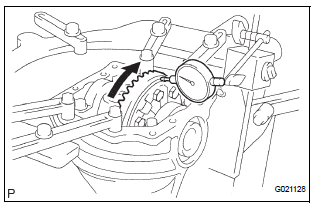
(a) Using a dial gauge , check the runout of the ring gear.
Maximum runout: 0.07 mm (0.0028 in.)
If the runout is greater than the maximum, replace the ring gear with a new one.
2. INSPECT DIFFERENTIAL RING GEAR BACKLASH
(a) Using a dial gauge, check the backlash of the ring gear.
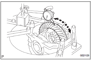
Backlash: 0.13 to 0.18 mm (0.0051 to 0.0071 in.)
If the backlash is not within the specification, adjust the side bearing preload or repair as necessary.
3. INSPECT RUNOUT OF REAR DRIVE PINION COMPANION FLANGE SUB-ASSEMBLY
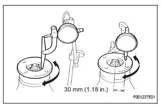
(a) Using a dial gauge, measure the runout of the companion flange vertically and horizontally.
Maximum runout: 0.10 mm (0.0039 in.)
 Disassembly
1. REMOVE REAR DIFFERENTIAL CARRIER COVER
(a) Remove the 8 bolts from the carrier cover.
(b) Using a brass bar and a hammer, separate the
carrier cover from rear differential carrier assembly ...
 Reassembly
1. INSTALL REAR DIFFERENTIAL PINION SHAFT
(a) Install the 2 thrust washers to the 2 side gears.
(b) Install the 2 side gears, 2 differential pinion gears, 2
differential pinion thrust washers ...
Other materials:
Window glass antenna wire
INSPECTION
1. INSPECT WINDOW GLASS ANTENNA WIRE
Inspect the wind glass antenna wire.
NOTICE:
When cleaning the glass, use a soft, dry cloth,
and wipe the glass in the direction of the wire.
Take care not to damage the wires. Do not use
detergents or glass cleaners with abrasiv ...
Installation
1. INSTALL NO. 2 REAR SEAT OUTER BELT ASSEMBLY
NOTICE:
Do not disassemble the retractor.
Check the degree of tilt when the No. 2 rear seat
outer belt assembly begins to lock the ELR.
Check that the belt does not lock within 15 of
tilt in all directions but that the be ...
DVD Player Mechanical Error/ DVD Insertion and Ejection Error/ DVD Reading
Abnormal
DTC 44-10 DVD Player Mechanical Error
DTC 44-11 DVD Insertion and Ejection Error
DTC 44-12 DVD Reading Abnormal
DESCRIPTION
TC No.
DTC Detection Condition
Trouble Area
44-10
A mechanical error in the DVD player is detected while
the DVD is not being insert ...
