Toyota Sienna Service Manual: Precaution
Caution:
|
NOTICE:
- Malfunction symptoms of the srs are difficult to confirm, so dtcs are the most important source of information when troubleshooting. When troubleshooting the srs, always inspect dtcs before disconnecting the battery.
- Even in the case of a minor collision when the srs does not deploy, the steering pad, front passenger airbag assembly, center airbag sensor assembly, front airbag sensor, front seat inner belt assembly, seat position sensor, occupant classification ecu, front seat side airbag assembly, side airbag sensor, curtain shield airbag assembly, rear airbag sensor, and front seat outer belt assembly should be inspected.
- Before repair work, remove the airbag sensor if any kind of shock is likely to occur to the airbag sensor during the repair.
- Never use srs parts from another vehicle. When replacing parts, replace them with new ones.
- Never disassemble or repair any of the following parts in order to reuse them. If any of these parts have been dropped, or a defect is found (e.G. Cracks, dents or any other defects) in any of the housings, brackets or connectors, then replace the part with a new one.
(A)steering pad
(b)front passenger airbag assembly
(c)front seat side airbag assembly
(d)curtain shield airbag assembly
(e)center airbag sensor assembly
(f) front airbag sensor
(g)front seat inner belt assembly
(h)seat position sensor
(i) occupant classification ecu
(j) side airbag sensor
(k)rear airbag sensor
(l) front seat outer belt assembly
- Use a volt/ohmmeter with high impedance (10 kΩ/V minimum) for troubleshooting the electrical circuits.
- Information labels are attached near the SRS components. Follow the instructions in the caution.
- After work on the SRS is completed, perform the SRS warning light check (See page RS-27).
- When the negative (-) terminal cable is disconnected
from the battery, the memory will be cleared. Because
of this, be sure to make a record of the contents
memorized in each system before starting work. When
work is finished, adjust each system as it was before.
Never attempt to avoid erasing vehicle system memories by using a backup power supply from outside the vehicle.
- If the vehicle is equipped with a mobile communication system, refer to the precaution in the INTRODUCTION section.
HINT: In the airbag system, the center airbag sensor assembly, front airbag sensors LH and RH, side airbag sensors LH and RH, rear airbag sensors LH and RH are collectively referred to as the airbag sensors.
1. HANDLING PRECAUTIONS FOR AIRBAG SENSORS
(a) Before starting the following operations, wait for at least 90 seconds after disconnecting the negative (- ) terminal cable from the battery: (1) Replacement of the airbag sensors (2) Adjustment of the front/rear doors of a vehicle equipped with a front seat side airbag and curtain shield airbag (fitting adjustment).
(b) When connecting or disconnecting the airbag sensor connectors, ensure that each sensor is installed in the vehicle.
(c) Do not use the airbag sensors which have been dropped during the operation or transportation.
(d) Do not disassemble the airbag sensors.
2. INSPECTION PROCEDURE FOR VEHICLE INVOLVED IN ACCIDENT
(a) When the airbag has not deployed, confirm the DTCs by checking the SRS warning light. If there is any malfunction in the SRS airbag system, perform troubleshooting.
(b) When any of the airbags have deployed, replace the airbag sensors and check the installation condition.
3. SRS CONNECTORS
(a) SRS connectors are located as shown in the following illustration.
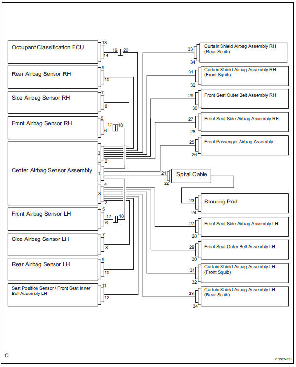
*1: Manual Seat
(b) All connectors in the SRS, except the seat position airbag sensor connector, are colored yellow to distinguish them from other connectors. These connectors have special functions, and are specially designed for the SRS. All SRS connectors use durable gold-plated terminals, and are placed in the locations shown on the previous page to ensure high reliability.
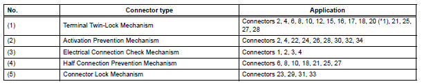
(1) Terminal twin-lock mechanism: All connectors with a terminal twin-lock mechanism have a two-piece component consisting of a housing and a spacer. This design enables the terminal to be locked securely by two locking devices (the retainer and the lance) to prevent terminals from coming out.
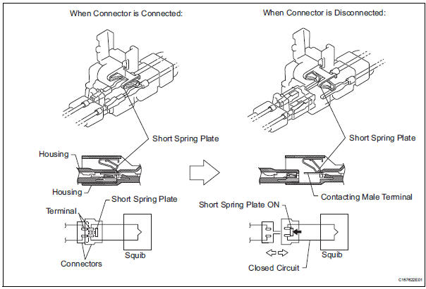
(2) Activation prevention mechanism: All connectors with an activation prevention mechanism contain a short spring plate. When these connectors are disconnected, the short spring plate creates a short circuit by automatically connecting the positive (+) and negative (-) terminals of the squib.
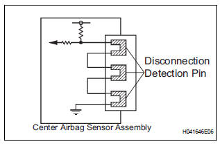
(3) Electrical connection check mechanism: This mechanism electrically checks that the connectors are connected correctly and completely. The electrical connection check mechanism is designed so that the disconnection detection pin connects with the diagnosis terminals when the connector housing lock is locked.
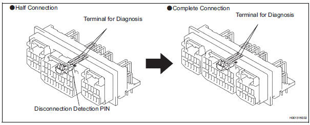
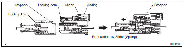
(4) Half connection prevention mechanism: If the connector is not completely connected, the connector is disconnected due to the spring operation so that no continuity exists.
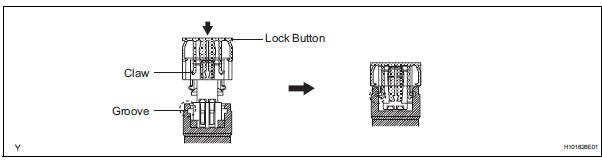
(5) Connector lock mechanism: Locking the connector lock button connects the connector securely.
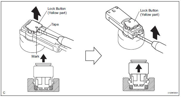
4. DISCONNECTION OF CONNECTORS FOR STEERING PAD, CURTAIN SHIELD AIRBAG ASSEMBLY, AND FRONT SEAT OUTER BELT ASSEMBLY
HINT: Tape up the screwdriver tip before use.
(a) Release the lock button (yellow part) of the connector using a screwdriver.
(b) Insert the screwdriver tip between the connector and the base, and then raise the connector.
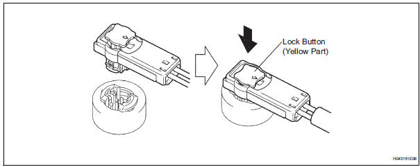
5. CONNECTION OF CONNECTORS FOR STEERING PAD, CURTAIN SHIELD AIRBAG ASSEMBLY, AND FRONT SEAT OUTER BELT ASSEMBLY
(a) Connect the connector.
(b) Push down securely on the lock button (yellow part) of the connector. (When locking, a click sound can be heard.)
6. DISCONNECTION OF CONNECTOR FOR FRONT PASSENGER AIRBAG ASSEMBLY
(a) Place a finger on the slider, slide the slider to release the lock, and then disconnect the connector.
7. CONNECTION OF CONNECTOR FOR FRONT PASSENGER AIRBAG ASSEMBLY
(a) Connect the connector as shown in the illustration.
(When locking, make sure that the slider returns to its original position and a click sound can be heard.)
HINT: When connected, the slider will slide. Be sure not to touch the slider while connecting, as it may result in an insecure fit.
8. DISCONNECTION OF CONNECTOR FOR FRONT SEAT SIDE AIRBAG ASSEMBLY
(a) Place a finger on the slider, slide the slider to release the lock, and then disconnect the connector.
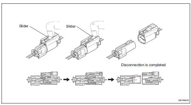
9. CONNECTION OF CONNECTOR FOR FRONT SEAT SIDE AIRBAG ASSEMBLY
(a) Connect the connector as shown in the illustration.
(When locking, make sure that the slider returns to its original position and a click sound can be heard.)
HINT: When connecting, the slider will side. Be sure not to touch the slider while connecting, as it may result in an insecure fit.

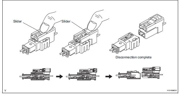
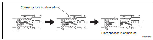
10. DISCONNECTION OF CONNECTORS FOR FRONT AIRBAG SENSOR, SIDE AIRBAG SENSOR AND REAR AIRBAG SENSOR
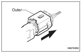
(a) While holding both the sides of the outer connector locking sleeve, slide the outer in the direction shown by the arrow.
(b) When the connector lock is released, the connectors are disconnected.
HINT: Be sure to hold both outer flank sides. Holding the top and bottom will make disconnection difficult.
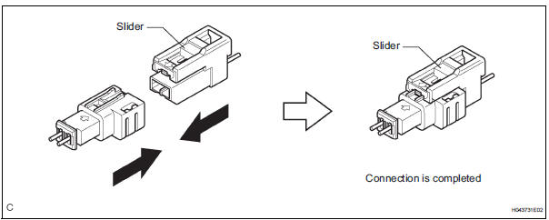
11. CONNECTION OF CONNECTORS FOR FRONT AIRBAG SENSOR, SIDE AIRBAG SENSOR AND REAR AIRBAG SENSOR
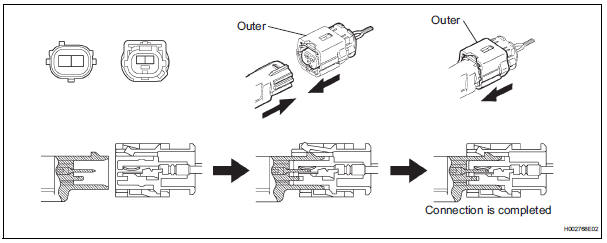
(a) Connect the connector as shown in the illustration (When locking, make sure that the outer returns to its original position and a click sound can be heard).
HINT: When connecting, the outer will slide. Be sure not to hold the outer while connecting, as it may result in an insecure fit.
 Airbag system
...
 Parts location
System diagram
...
Other materials:
How to proceed with
troubleshooting
The intelligent tester can be used in steps 4, 6, 8 and 9.
1 VEHICLE BROUGHT TO WORKSHOP
2 CUSTOMER PROBLEM ANALYSIS
3 PASSENGER AIRBAG ON/OFF INDICATOR CHECK
4 DTCs CHECK (Present and Past DTCs)
Check for DTCs.
Result
5 DTCs CHART
6 CIRCUIT INSPECTION
7 REPAIR
8 CLEAR DTCs (Present ...
How to proceed with
troubleshooting
HINT:
Troubleshooting of the wireless door lock control system is
based on the premise that the power door lock system, the
power slide door system, the power back door system and
the power window system are operating normally.
Therefore, before troubleshooting the wireless door lo ...
Smart key system
The following operations can be performed simply by carrying
the electronic key on your person, for example in your pocket.
The driver should always carry the electronic key.
Locks and unlocks the doors
Front door handles
Sliding door handles
Back door
Starts and stops the ...
