Toyota Sienna Service Manual: Removal
1. Remove front wheel
2. Remove front wiper arm head cap
Hint: (see page ww-3)
3. Remove fr wiper arm rh
HINT: (See page WW-3)
4. Remove fr wiper arm lh
HINT: (See page WW-3)
5. Remove cowl top ventilator louver subassembly
Hint: (see page ww-3)
6. Remove windshield wiper motor & link assembly
Hint: (see page ww-3)
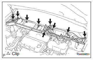
7. Remove cowl top panel sub-assembly outer front
HINT: When removing or installing the front shock absorber with coil spring RH, it is necessary to remove the cowl top panel sub-assembly outer front
(a) Disconnect the wire harness from the cowl top panel sub-assembly outer front.
(b) Remove the 9 bolts, cowl top brace and cowl top panel sub-assembly outer front.
8. REMOVE FRONT STABILIZER LINK ASSEMBLY LH
(a) Remove the nut and disconnect the front stabilizer link assembly LH from the shock absorber assembly front LH.
HINT: If the ball joint turns together with the nut, use a hexagon (6 mm) wrench to hold the stud.
9. REMOVE FRONT SHOCK ABSORBER WITH COIL SPRING
(a) Loosen the lock nut.
NOTICE:
- Do not loosen the nut except for the purpose of disassembling the shock absorber assembly front LH with coil spring.
- Do not remove the lock nut.
(b) Remove the bolt, and disconnect the front flexible hose No.1 and speed sensor front LH.
(c) Remove the 2 nuts and 2 bolts on the lower side of the front shock absorber with coil spring
NOTICE: When removing the bolt, hold the nut not to rotate.
(d) Remove the 3 nuts on the upper side of the front shock absorber with coil spring.
(e) Remove the front shock absorber with the coil spring.
 Front shock absorber with coil spring
COMPONENTS
...
 Disassembly
1. FIX FRONT SHOCK ABSORBER WITH COIL SPRING
(a) Install 2 nuts and a bolt to the bracket at the lower
side of the front shock absorber with coil spring and
secure it in a vise.
2. REMOVE FRONT SU ...
Other materials:
Removal
1. REMOVE FRONT WHEELS
2. REMOVE FRONT STABILIZER LINK ASSEMBLY LH
HINT:
(See page SP-26)
3. REMOVE FRONT STABILIZER LINK ASSEMBLY RH
HINT:
Remove the RH side by the same procedures as the LH
side.
4. REMOVE CENTER EXHAUST PIPE ASSEMBLY
HINT:
(See page EX-8)
5. REMOVE NO. 1 FRONT STABILIZ ...
Perform zero point calibration of yaw rate and deceleration sensor (when
using sst check wire)
NOTICE:
While obtaining the zero point, do not vibrate the
vehicle by tilting, moving or shaking it and keep it
in a stationary condition. (Do not turn the ignition
switch to the ON position.)
Be sure to do this on a level surface (with an
inclination of less than 1 %).
(a) Proc ...
Tachometer Malfunction
DESCRIPTION
The meter CPU receives the engine revolution signal from the ECM via the
direct lines. The meter CPU
displays engine revolution data that is calculated based on the data received
from the ECM.
WIRING DIAGRAM
INSPECTION PROCEDURE
1 PERFORM ACTIVE TEST BY INTELLIGENT TESTER
...
