Toyota Sienna Service Manual: Side Airbag Sensor Assembly LH Circuit Malfunction
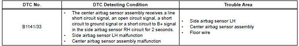
DTC B1141/33 Side Airbag Sensor Assembly LH Circuit Malfunction
DESCRIPTION
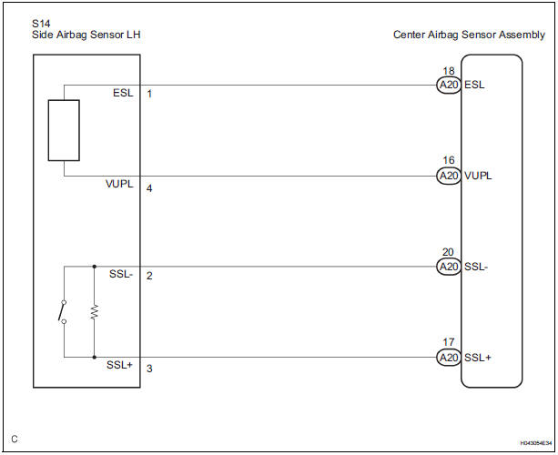
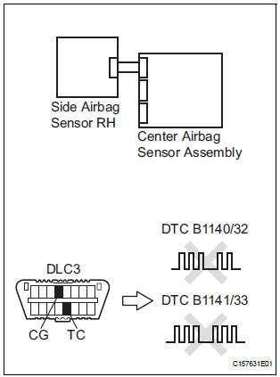
The side airbag sensor LH circuit consists of the center airbag sensor assembly and side airbag sensor LH.
If the center airbag sensor assembly receives signals from the side airbag sensor LH, it judges whether or not the SRS should be activated.
DTC B1141/33 is recorded when a malfunction in the side airbag sensor LH circuit is detected.
WIRING DIAGRAM
INSPECTION PROCEDURE
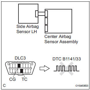
1 CHECK DTC
- Turn the ignition switch to the ON position, and wait for at least 60 seconds.
- Clear the DTCs stored in memory.
- Turn the ignition switch to the LOCK position.
- Turn the ignition switch to the ON position, and wait for at least 60 seconds.
- Check the DTCs.
OK: DTC B1141/33 is not output.
HINT: Codes other than DTC B1141/33 may be output at this time, but they are not related to this check.
USE SIMULATION METHOD TO CHECK2 CHECK CONNECTION OF CONNECTORS
- Turn the ignition switch to the LOCK position.
- Disconnect the negative (-) terminal cable from the battery, and wait for at least 90 seconds.
- Check that the connectors are properly connected to the center airbag sensor assembly and the side airbag sensor LH.
OK: The connectors are connected.
3 CHECK FLOOR WIRE (OPEN)
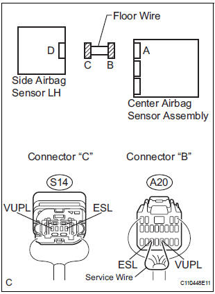
- Disconnect the connectors from the center airbag sensor assembly and the side airbag sensor LH.
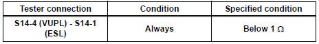
- Using a service wire, connect A20-16 (VUPL) and A20-
18 (ESL) of connector "B".
NOTICE: Do not forcibly insert a service wire into the terminals of the connector when connecting.
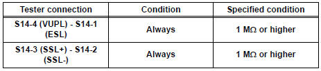
- Measure the resistance according to the value(s) in the table below.
Standard resistance
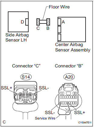
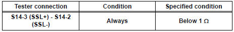
- Using a service wire, connect A20-17 (SSL+) and A20-
20 (SSL-) of connector "B".
NOTICE: Do not forcibly insert a service wire into the terminals of the connector when connecting.
- Measure the resistance according to the value(s) in the table below.
Standard resistance
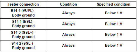
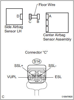
4 CHECK FLOOR WIRE (SHORT TO B+)
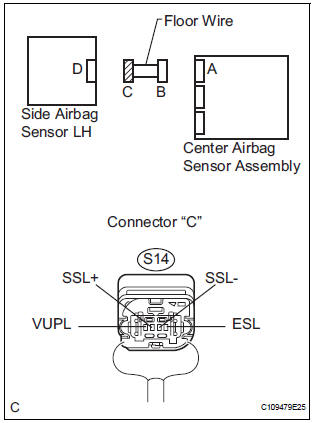
- Disconnect the service wire from connector "B".
- Connect the negative (-) terminal cable to the battery, and wait for at least 2 seconds.
- Turn the ignition switch to the ON position.
- Measure the voltage according to the value(s) in the table below.
Standard voltage
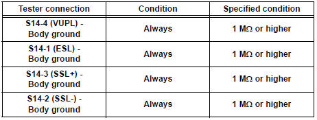
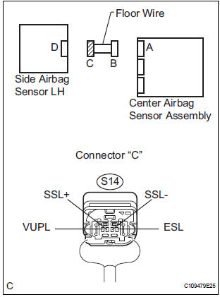
5 CHECK FLOOR WIRE (SHORT TO GROUND)
- Turn the ignition switch to the LOCK position.
- Disconnect the negative (-) terminal cable from the battery, and wait for at least 90 seconds.
- Measure the resistance according to the value(s) in the table below.
Standard resistance
6 CHECK FLOOR WIRE (SHORT)
- Measure the resistance according to the value(s) in the table below
Standard resistance
7 CHECK SIDE AIRBAG SENSOR LH
- Connect the connector to the center airbag sensor assembly.
- Interchange the side airbag sensor RH with LH and connect the connectors to them.
- Connect the negative (-) terminal cable to the battery, and wait for at least 2 seconds.
- Turn the ignition switch to the ON position, and wait for at least 60 seconds.
- Clear the DTCs stored in memory.
- Turn the ignition switch to the LOCK position.
- Turn the ignition switch to the ON position, and wait for at least 60 seconds.
- Check the DTCs.
Result
HINT: Codes other than DTC B1140/32 and B1141/33 may be output at this time, but they are not related to this check.
USE SIMULATION METHOD TO CHECK
 Side Airbag Sensor Assembly RH Circuit Malfunction
DTC B1140/32 Side Airbag Sensor Assembly RH Circuit Malfunction
DESCRIPTION
The side airbag sensor RH circuit consists of the center airbag sensor
assembly and side airbag sensor
RH.
If the ce ...
 Front Airbag Sensor RH Circuit Malfunction
DTC B1148/36 Front Airbag Sensor RH Circuit Malfunction
DESCRIPTION
The front airbag sensor RH circuit consists of the center airbag sensor
assembly and front airbag sensor
RH. If the center airb ...
Other materials:
Inspection
1. INSPECT CRANKSHAFT POSITION SENSOR
Using an ohmmeter, measure the resistance
between the terminals.
Standard resistance
NOTICE:
"Cold" and "Hot" mean the temperature of the
coils themselves.
"Cold" is from -10C (14F) to 50C (122F ...
Throttle / Pedal Position Sensor / Switch "A/B"
Circuit
DTC P0120 Throttle / Pedal Position Sensor / Switch "A"
Circuit
DTC P0122 Throttle / Pedal Position Sensor / Switch "A"
Circuit Low Input
DTC P0123 Throttle / Pedal Position Sensor / Switch "A"
Circuit High Input
DTC P0220 Throttle / Pedal Position Sensor / Switch ...
Child restraint systems with a top tether strap (second seat)
Secure the child restraint system
using the seat belt or
LATCH anchors, and adjust the
head restraint to the uppermost
position.
*: Ottoman seat only
Latch the hook onto the anchor
bracket and tighten the top
tether strap.
Make sure the top tether strap is
secure ...
