
Toyota Sienna 2010-2026 Owners Manual: “Phone/Message Settings� screen
To display the screen shown below, press the “SETUP� button, and select “Phone� on the “Setup� screen.
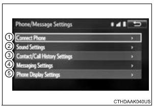
- Set the phone connection
- Setting the sound
- Contact/Call History Settings
- Set the message settings
- Set the phone display
 Bluetooth® phone
settings
Bluetooth® phone
settings
You can adjust the hands-free system to your desired settings. ...
 Sound setting
Display the “Phone/Message Settings� screen.
Select “Sound Settings� on the “Phone/Message Settings� screen.
Set the desired ringtone.
Adjust the ringtone volume.
Adjus ...
Other materials:
Installation
1. INSTALL REAR DOOR GLASS WEATHERSTRIP
Install the rear door glass weatherstrip.
2. INSTALL SLIDE DOOR WINDOW ASSEMBLY
3. INSTALL REAR DOOR GLASS RUN
4. INSTALL REAR DOOR TRIM BOARD SUBASSEMBLY
5. INSTALL SIDE TRIM BOARD COVER REAR
6. INSTALL REAR DOOR WINDOW FRAME SUBASSEMBLY
7. INSTA ...
Engine immobiliser system
PARTS LOCATION
SYSTEM DESCRIPTION
The engine immobiliser system has been designed to prevent
the vehicle from being stolen. This system uses a
transponder key ECU that stores the key code of the
authorized ignition key. If an attempt is made to start the
engine using a non-authorized key, ...
Rear ceiling lights
Turns the lights on/off
When the personal/interior light
main switch is in the off position,
the rear ceiling lights will not turn
on even if the switch is on.
Adjusting the rear personal/interior lights angle (if equipped)
Push the edge of the light lens.
Illuminated entry system
...
