Toyota Sienna Service Manual: Passenger Side Outer Mirror ECU
DTC B1208 Passenger Side Outer Mirror ECU
DESCRIPTION
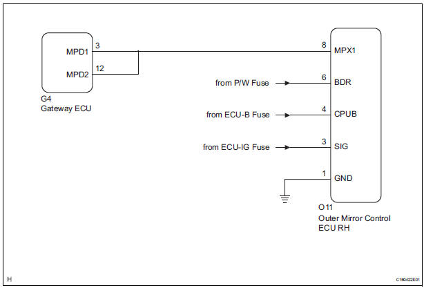
This DTC is detected when communication between the outer mirror control ECU RH and multiplex network gateway ECU stops for more than 10 seconds.
|
DTC No. |
DTC Detecting Condition |
Trouble Area |
|
B1208 |
Passenger side outer mirror ECU communication stops |
|
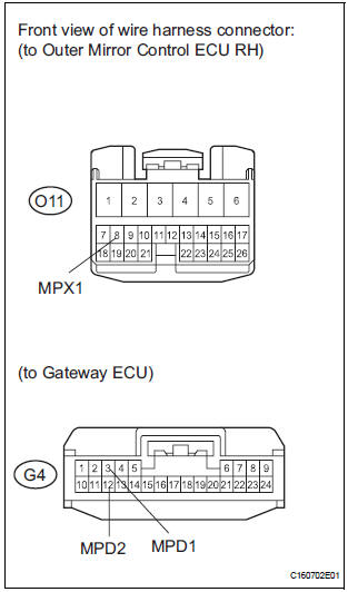
WIRING DIAGRAM
INSPECTION PROCEDURE
1 CHECK HARNESS AND CONNECTOR (OUTER MIRROR CONTROL ECU RH - BATTERY)
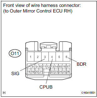
- Disconnect the O11 ECU connector.
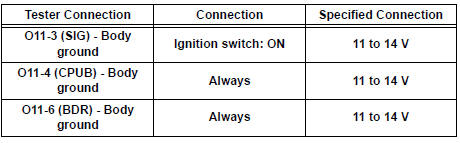
- Measure the voltage according to the value(s) in the table below.
Standard voltage
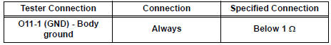
2 CHECK HARNESS AND CONNECTOR (OUTER MIRROR CONTROL ECU RH - GROUND)
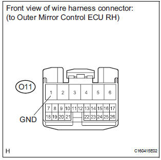
- Measure the resistance according to the value(s) in the table below.
Standard resistance
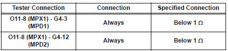
3 CHECK COMMUNICATION LINE
- Disconnect the G4 ECU connector.
- Measure the resistance according to the value(s) in the table below.
Standard resistance
Result
REPLACE OUTER MIRROR CONTROL ECU RH
 MPX Body ECU Stop
DTC B1200 MPX Body ECU Stop
DESCRIPTION
This DTC is detected when communication between the multiplex network body
ECU and the multiplex
network gateway ECU stops for more than 10 seconds.
...
 Driver Side Outer Mirror
DTC B1209 Driver Side Outer Mirror
DESCRIPTION
This DTC is detected when communication between the outer mirror control ECU
LH and multiplex
network gateway ECU stops for more than 10 seconds
...
Other materials:
Display check mode
HINT:
This mode checks the color display on the display.
Illustrations may differ from the actual vehicle depending
on the device settings and options. Therefore, some
detailed areas may not be shown exactly the same as on
the actual vehicle.
1. ENTER DIAGNOSTIC MODE
2. D ...
Intake Air Temperature Sensor Gradient Too
High
DTC P0111 Intake Air Temperature Sensor Gradient Too
High
DESCRIPTION
The Intake Air Temperature (IAT) sensor, mounted on the Mass Air Flow (MAF)
meter, monitors the IAT.
The IAT sensor has a built-in thermistor with a resistance that varies according
to the temperature of the
intake ...
Disassembly
1. REMOVE REAR SEAT LEG COVER LH
Remove the 2 screws and seat leg cover.
2. REMOVE REAR SEAT LEG COVER RH
Remove the 2 screws and seat leg cover.
3. REMOVE REAR SEAT LEG SIDE COVER LH
Remove the 2 screws and leg side cover.
4. REMOVE LH SEAT REAR SEAT LOCK COVE ...
