Toyota Sienna Service Manual: Adjustment
HINT: On the RH side, use the same procedures as on the LH side.
1. INSPECT SLIDE DOOR PANEL SUB-ASSEMBLY LH
- Check that the clearance is within the standard range.
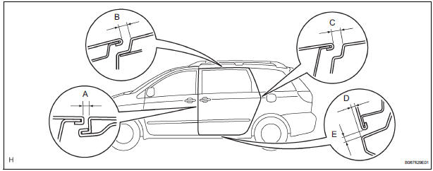
Standard

2. ADJUST SLIDE DOOR PANEL SUB-ASSEMBLY LH
- Using the SST, horizontally and vertically adjust the
door by loosening the hinge center bolts.
SST 09812-00010, 09812-00020
- Tighten the hinge assembly center bolts after the
adjustment.
Torque: 31 N*m (306 kgf*cm, 23 ft.*lbf)
- Vertically adjust the front side of the door by loosening the roller lower bolts.
- Tighten the roller lower bolts after the adjustment.
Torque: 31 N*m (306 kgf*cm, 23 ft.*lbf)
- Horizontally adjust the front lower side of the door by loosening the roller lower bolts.
- Tighten the roller lower bolts after the adjustment.
Torque: 31 N*m (306 kgf*cm, 23 ft.*lbf)
- Horizontally adjust the front upper side of the door by loosening the roller upper bolts.
- Tighten the roller assembly lower bolts after the
adjustment.
Torque: 8.5 N*m (82 kgf*cm, 73 in.*lbf)
- Adjust the position of the door lock striker by slightly loosening the striker mounting screws and hitting the striker with a plastic-faced hammer.
- Tighten the striker mounting screws after the
adjustment.
Torque: 23 N*m (235 kgf*cm, 17 ft.*lbf)
- Adjust the position of the front lock striker by slightly loosening the striker mounting screws and hitting the striker with a plastic-faced hammer.
- Tighten the striker mounting screws after the
adjustment.
Torque: 23 N*m (235 kgf*cm, 17 ft.*lbf)
- Adjust the position of the down stopper by moving the male stopper, so that the male stopper can enter smoothly.
- Tighten the female stopper mounting bolts after the
adjustment.
Torque: 5.5 N*m (58 kgf*cm, 49 in.*lbf)
 Disassembly
HINT:
On the RH side, use the same procedures as on the LH side.
1. REMOVE REAR DOOR WINDOW FRAME MOULDING
REAR LH (See page ET-30)
2. REMOVE REAR DOOR WINDOW FRAME MOULDING
SUB-ASSEMBLY LH (See ...
 Reassembly
1. INSTALL REAR DOOR WIRE SUB-ASSEMBLY LH
Install the wire.
NOTICE:
When installing the wire, push the areas where
the clips are installed in order to prevent
damage and deformation.
...
Other materials:
Removal
1. Disconnect cable from negative battery
terminal
2. REMOVE HEATED OXYGEN SENSOR (for Bank 1
Sensor 2) (See page EC-32)
3. REMOVE TAIL EXHAUST PIPE ASSEMBLY
(a) Remove the 2 bolts.
(b) Disconnect the 3 exhaust pipe supports and remove
the tail exhaust pipe assembly.
(c) Remove the gas ...
Engine rear oil seal
Components
Removal
1. REMOVE AUTOMATIC TRANSAXLE ASSEMBLY (for
2WD)
HINT:
See page AX-163.
2. REMOVE AUTOMATIC TRANSAXLE ASSEMBLY (for
4WD)
HINT:
See page AX-167.
3. REMOVE DRIVE PLATE AND RING GEAR SUBASSEMBLY
(a) Using SST, hold the crankshaft.
SST 09213-70011 (09213-70020), ...
Engine compartment
Items
Check points
Battery
Check connections
Brake fluid
Is the brake fluid at the correct level?
Engine coolant
Is the engine coolant at the correct
level?
Engine oil
Is the engine oil at the correct level?
Exhaust system ...
