Toyota Sienna Service Manual: Removal
1. Disconnect cable from negative battery terminal
2. REMOVE HEATED OXYGEN SENSOR (for Bank 1 Sensor 2) (See page EC-32)
3. REMOVE TAIL EXHAUST PIPE ASSEMBLY
(a) Remove the 2 bolts.
(b) Disconnect the 3 exhaust pipe supports and remove the tail exhaust pipe assembly.
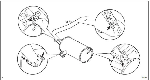
(c) Remove the gasket from the center exhaust pipe assembly.
4. REMOVE CENTER EXHAUST PIPE ASSEMBLY
(a) Remove the 2 bolts and 2 compression springs.
(b) Disconnect the 2 exhaust pipe supports and remove the center exhaust pipe assembly
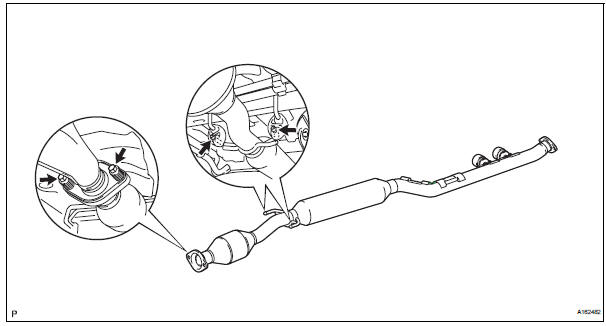
(c) Remove the gasket from the front exhaust pipe assembly.
5. REMOVE FRONT EXHAUST PIPE ASSEMBLY
(a) Disconnect the heated oxygen sensor (for bank 2 sensor 2) connector.
(b) Remove the 6 nuts and front exhaust pipe assembly.
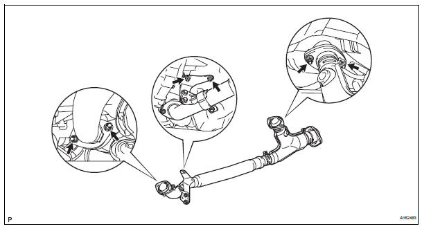
(c) Remove the 2 gaskets from the front exhaust pipe assembly.
6. REMOVE NO. 1 EXHAUST PIPE SUPPORT BRACKET
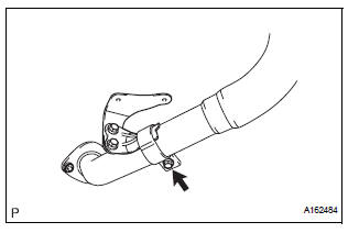
(a) Remove the bolt and No. 1 exhaust pipe support bracket.
7. REMOVE HEATED OXYGEN SENSOR (for Bank 2 Sensor 2) (See page EC-33)
 Exhaust pipe (for 2wd)
Components
...
 Installation
1. Install heated oxygen sensor (for bank 2
sensor 2) (see page ec-34)
2. Install front exhaust pipe assembly
(a) Install 2 new gaskets to the front exhaust pipe
assembly.
(b) Install the front ...
Other materials:
How to proceed with
troubleshooting
HINT:
Use these procedures to troubleshoot the power door lock
control system.
The intelligent tester should be used in steps 4 and 5.
1 VEHICLE BROUGHT TO WORKSHOP
2 CUSTOMER PROBLEM ANALYSIS CHECK
HINT:
In troubleshooting, confirm that the problem symptoms
have ...
Inspection
1. INSPECT BRAKE CYLINDER AND PISTON
(a) Check the brake cylinder bore and front disc brake
piston for rust or scoring.
2. INSPECT PAD LINING THICKNESS
(a) Using a ruler, measure the pad lining thickness.
Standard thickness:
12.0 mm (0.472 in.)
Minimum thickness:
1.0 mm (0.039 in.)
3. ...
Installation
1. INSTALL ENGINE OIL COOLER
(a) Clean the oil cooler contact surface on the cooler
mounting.
(b) Install a new O-ring to the oil cooler.
(c) Install the oil cooler assembly with the union bolt.
Torque: 68 N*m (693 kgf*cm, 50 ft.*lbf)
Install the 2 water by-pass hoses with the bolt ...
