Toyota Sienna Service Manual: Air-fuel ratio (a/f) and heated oxygen (ho2) sensor heater monitors (front a/f and rear ho2 sensor type)
(a) Preconditions
The monitor will not run unless:
- The MIL is OFF.
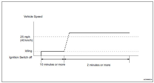
(b) Drive Pattern
(1) Connect an intelligent tester to the DLC3.
(2) Turn the ignition switch to the ON position.
(3) Clear the DTCs.
(4) Start the engine.
(5) Allow the engine to idle for 10 minutes or more.
(6) Drive the vehicle at 25 mph (40 km/h) or more for at least 2 minutes.
(c) Monitor Status
(1) Check the Readiness Monitor status displayed on the tester or scan tool.
If the status does not switch to COMPL (complete), make sure that the preconditions have been met, and repeat the Drive Pattern.
 A/F sensor and ho2s monitors
(a) Preconditions
The monitor will not run unless:
2 minutes or more have elapsed since the engine
was started.
The Engine Coolant Temperature (ECT) is 75°C
(167°F) or more.
Cumulative ...
 Problem symptoms table
HINT:
When a malfunction is not confirmed by a DTC (Diagnostic
Trouble Code) check and the cause of problem cannot be
identified through a basic inspection, troubleshoot according
to the priority ...
Other materials:
Cooling fan ecu
ON-VEHICLE INSPECTION
1. INSPECT COOLING FAN ECU
(a) Inspect the input voltage.
(1) Disconnect the cooling fan ECU connector.
(2) Turn the ignition switch to the ON position.
Check the voltage of the +B terminal of the
disconnected wire harness side connector.
Standard voltage:
9 t ...
Open in Driver Side Squib 2nd Step Circuit
DTC B1181/18 Open in Driver Side Squib 2nd Step Circuit
DESCRIPTION
The driver side squib 2nd step circuit consists of the center airbag sensor
assembly, the spiral cable and
the steering pad.
The circuit instructs the SRS to deploy when deployment conditions are met.
DTC B1181/18 is reco ...
Removal
1. DISCONNECT CABLE FROM NEGATIVE BATTERY TERMINAL
2. REMOVE STEERING WHEEL NO. 2 LOWER COVER
3. REMOVE STEERING WHEEL NO. 3 LOWER COVER
4. REMOVE HONE BUTTON ASSEMBLY
5. REMOVE STEERING PAD SWITCH LH
Disconnect the connector.
Disconnect the connector of cruise control main
swi ...
