Toyota Sienna Service Manual: Inspection
1. INSPECT PARK/NEUTRAL POSITION SWITCH ASSEMBLY OPERATION
(a) Apply the parking brake and turn the ignition switch to the ON position.
(b) Depress the brake pedal and check that the engine starts only when the shift lever is in the N or P position and the engine does not start when the shift lever is in other positions.
(c) Check that the back up light comes on and the reverse warning buzzer sounds only when the shift lever is in the R position and the light and buzzer do not operate when the shift lever is in other positions.
(d) If a failure is found, check the park/neutral position switch for continuity.
2. INSPECT PARK/NEUTRAL POSITION SWITCH ASSEMBLY
(a) Jack up the vehicle.
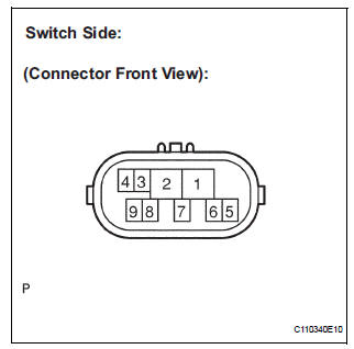
(b) Disconnect the park/neutral position switch connector.
(c) Measure the resistance according to the value(s) in the table below when the shift lever is moved to each position.
Resistance 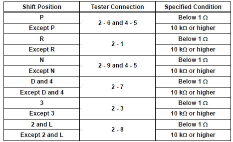
ADJUSTMENT
1. ADJUST PARK/NEUTRAL POSITION SWITCH ASSEMBLY
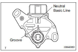
(a) Loosen the 2 bolts of the park/neutral position switch and move the shift lever to the N position.
(b) Align the groove with the neutral basic line.
(c) Hold the switch in position and tighten the 2 bolts.
Torque: 5.4 N*m (55 kgf*cm, 48 in.*lbf) (d) After adjustment, perform the inspection described in park/neutral position switch assembly operation.
 Removal
1. REMOVE BATTERY
2. REMOVE AIR CLEANER ASSEMBLY
HINT:
(See page EM-26)
3. SEPARATE TRANSMISSION CONTROL CABLE ASSEMBLY
(a) Remove the nut from the control shaft lever.
(b) Disconnect the ...
 Installation
1. INSTALL PARK/NEUTRAL POSITION SWITCH ASSEMBLY
(a) Install the park/neutral position switch to the manual
valve shaft.
(b) Temporarily install the 2 bolts.
(c) Place a new lock plate a ...
Other materials:
Disassembly
1. REMOVE SIDE DEFROSTER NOZZLE DUCT NO.1
(a) Remove the 2 screws <C> and defroster nozzle
duct No. 1.
2. REMOVE SIDE DEFROSTER NOZZLE DUCT NO.2
(a) Remove the 2 screws <C> and defroster nozzle
duct No. 2.
3. REMOVE DEFROSTER NOZZLE ASSEMBLY
(a) Remove the 4 screws <C> and d ...
Vehicle Speed Signal Circuit between Radio Receiver and Combination
Meter
DESCRIPTION
This circuit is necessary for the ASL (Auto Sound Leveliser) built into the
radio receiver.
Speed signals are received from the combination meter and used for the ASL.
The ASL function automatically adjusts the sound data in order to enable hearing
the clear audio sound
even ...
Air-fuel ratio (a/f) and heated oxygen (ho2)
sensor heater monitors (front a/f and rear ho2 sensor
type)
(a) Preconditions
The monitor will not run unless:
The MIL is OFF.
(b) Drive Pattern
(1) Connect an intelligent tester to the DLC3.
(2) Turn the ignition switch to the ON position.
(3) Clear the DTCs.
(4) Start the engine.
(5) Allow the engine to idle for 10 minutes or more.
...
