Toyota Sienna Service Manual: Installation
1. INSTALL REAR AXLE HUB & BEARING ASSEMBLY LH
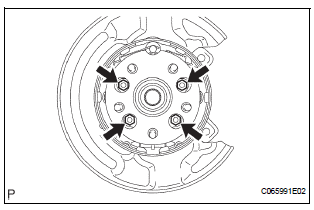
(a) Install the hub & bearing assembly LH with the 4 bolts.
Torque: 56 N*m (571 kgf*cm, 41 ft.*lbf)
2. INSPECT BEARING BACKLASH (See page AH-19)
3. INSPECT AXLE HUB DEVIATION (See page AH-19)
4. INSTALL REAR DRIVE SHAFT ASSEMBLY LH (See page DS-26)
5. INSTALL SPEED SENSOR REAR LH
(a) Install the bolt, connect the speed sensor rear LH.
Torque: 8.0 N*m (82 kgf*cm, 71 in.*lbf)
NOTICE:
- Be careful not to damage the speed sensor.
- Prevent foreign matter from attaching to the speed sensor.
- Do not twist the sensor wire when installing the sensor.
6. INSTALL REAR DISC
7. INSTALL REAR DISC BRAKE CALIPER ASSEMBLY LH
(a) Install the rear disc brake caliper assembly LH with the 2 bolts.
Torque: 88 N*m (900 kgf*cm, 65 ft.*lbf)
8. INSTALL REAR AXLE SHAFT LH NUT (See page DS- 26)
9. INSTALL REAR WHEEL Torque: 103 N*m (1,050 kgf*cm, 76 ft.*lbf)
10. CHECK ABS SPEED SENSOR SIGNAL
(a) ABS WITH EBD & BA & TRAC & VSC SYSTEM (See page BC-72).
 Removal
HINT:
Replace the RH side by the same procedures as the LH side.
1. REMOVE REAR WHEEL
2. REMOVE REAR AXLE SHAFT LH NUT (See page DS-
22)
3. SEPARATE REAR DISC BRAKE CALIPER
ASSEMBLY LH
(a) Remo ...
 Suspension
...
Other materials:
Power slide door warning buzzer
INSPECTION
1. INSPECT POWER SLIDE DOOR WARNING BUZZER LH
Check the resistance of the buzzer.
Resistance
If the result is not as specified, replace the buzzer.
NOTICE:
The circuit that causes the buzzer to sound is
built into the slide door ECU, not around the
buzzer.
Direct ...
Diagnosis Circuit
DESCRIPTION
DTC output mode is set by connecting terminals TC and CG of the DLC3.
DTCs are displayed by blinking the SRS warning light.
HINT:
When each warning light stays blinking, a ground short in the
wiring of terminal TC of the DLC3 or an
internal ground short in each ECU is ...
Steering Angle Sensor Zero Point Malfunction
DTC C1290/66 Steering Angle Sensor Zero Point Malfunction
DESCRIPTION
The skid control ECU acquires steering angle sensor zero point every time the
ignition switch is turned to
the ON position and the vehicle is driven at 35 km/h (22 mph) or more for
approximately 5 seconds. The
ECU also sto ...
