Toyota Sienna Service Manual: Installation
1. INSTALL RACK & PINION POWER STEERING GEAR ASSEMBLY
(a) Install the power steering gear assembly with the 2 bolts and nuts.
Torque: 70 N*m (714 kgf*cm, 52 ft.*lbf)
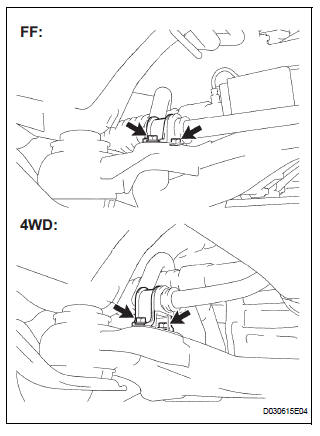
2. CONNECT PRESSURE FEED TUBE ASSEMBLY
(a) Connect the pressure feed tube assembly to the power steering gear assembly.
(b) Install the clip.
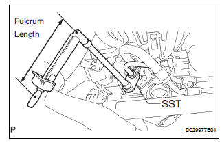
(c) Using SST, connect the return tube assembly to the power steering gear assembly.
SST 09023-12701 Torque: 22.5 N*m (229 kgf*cm, 17 ft.*lbf)
HINT
- Use a torque wrench with a fulcrum length of 300 mm (11.81 in.).
- This torque value is effective when SST is parallel to the torque wrench.
(d) Install the tube clamp with the bolt.
Torque: 9.8 N*m (100 kgf*cm, 87 in.*lbf)
(e) Install the tube clamp with the nut.
Torque: 9.8 N*m (100 kgf*cm, 87 in.*lbf)
3. INSTALL FRONT STABILIZER BRACKET NO.1 LH
(a) Install the stabilizer bracket No. 1 with the 2 bolts.
Torque: 17 N*m (173 kgf*cm, 12 ft.*lbf)
4. INSTALL FRONT STABILIZER BRACKET NO.1 RH
HINT: Perform the same procedure on the other side.
5. INSTALL FRONT STABILIZER LINK ASSEMBLY LH
6. INSTALL FRONT STABILIZER LINK ASSEMBLY RH
HINT: Perform the same procedure on the other side.
7. INSTALL STEERING INTERMEDIATE SHAFT ASSEMBLY
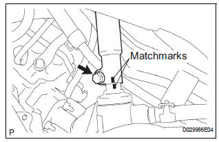
(a) Align matchmarks on the intermediate shaft assembly and power steering gear assembly.
(b) Install the bolt.
Torque: 36 N*m (367 kgf*cm, 27 ft.*lbf)
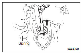
(c) Install the dust cover.
HINT: Ensure that the springs are installed tightly.
8. INSTALL TIE ROD ASSEMBLY LH
9. INSTALL TIE ROD ASSEMBLY RH
HINT: Perform the same procedure on the other side.
10. INSTALL FRONT WHEEL Torque: 103 N*m (1,050 kgf*cm, 76 ft.*lbf)
11. INSPECT CENTER FRONT WHEEL
12. INSPECT STEERING WHEEL CENTER POINT
13. ADD POWER STEERING FLUID
14. BLEED POWER STEERING FLUID
HINT: (See page PS-6)
15. INSPECT FOR POWER STEERING FLUID LEAK
16. INSPECT AND ADJUST FRONT WHEEL ALIGNMENT
HINT: (See page SP-4)
 Reassembly
1. INSTALL RACK STEERING PISTON RING
(a) Coat a new O-ring with power steering fluid and
install it onto the power steering rack.
(b) Expand a new rack steering piston ring with your
fingers ...
 Air conditioning
...
Other materials:
Crankshaft position sensor
Components
Removal
1. Remove compressor and magnetic clutch
HINT:
(See page AC-227 )
2. REMOVE CRANKSHAFT POSITION SENSOR
(a) Disconnect the crankshaft position sensor
connector.
(b) Remove the bolt, and then remove the crankshaft
position sensor.
INSPECTION
1. INSPECT CRANKSHAFT ...
SRS Warning Light does not Come ON
DESCRIPTION
WIRING DIAGRAM
INSPECTION PROCEDURE
1 CHECK BATTERY
Measure the voltage of the battery.
Standard voltage:
11 to 14 V
2 CHECK CONNECTORS
Turn the ignition switch to the LOCK position.
Disconnect the negative (-) terminal cable from the
battery, and wait for at le ...
Reassembly
1. INSTALL NO. 2 SEAT LEG SUB-ASSEMBLY
Install the No. 2 seat leg sub-assembly with the 3
bolts and nut.
Torque: 19 N*m (194 kgf*cm, 14 ft.*lbf)
NOTICE:
Tighten the bolts and nuts in the order shown in
the illustration.
Install the 3 clamps.
2. INSTALL NO. 2 SEAT ...
