Toyota Sienna Service Manual: Reassembly
1. APPLY HIGH TEMPERATURE GREASE
(a) Apply the high temperature grease to the surface on which the shoe and backing plate attach.
2. INSTALL PARKING BRAKE SHOE LEVER LH
(a) Install the shoe lever and shim to the rear shoe with a new C-washer.
(b) Using a feeler gauge, measure the clearance.
Standard clearance: Less than 0.35 mm (0.0138 in.)
If the clearance is not within the specification,
replace the shim with one of the correct size.
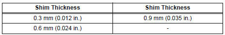
(c) Install the correct side shim with a new C-washer.
(d) Remeasure the clearance.
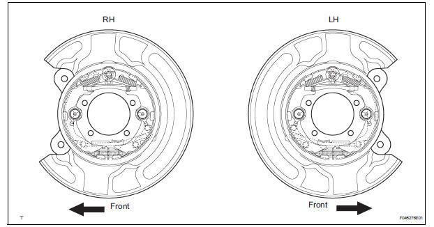
3. INSTALL PARKING BRAKE SHOE ASSEMBLY LH NO.2
(a) Using needle-nose pliers, connect the parking brake cable No. 3 to the parking brake shoe lever.
(b) Install the parking brake shoe assembly LH No. 2 with the shoe hold-down compression spring pin No. 2, shoe hold-down compression spring and 2 cups.
4. INSTALL PARKING BRAKE SHOE ADJUSTING SCREW SET
(a) Apply the high temperature grease to the adjusting bolt.
(b) Install the parking brake shoe adjusting screw set LH.
5. INSTALL PARKING BRAKE SHOE STRUT LH
6. INSTALL PARKING BRAKE SHOE ASSEMBLY LH NO.1
(a) Install the parking brake shoe assembly LH No. 1 with the shoe hold-down compression spring pin No. 1, shoe hold-down compression spring and 2 cups.
(b) Install the tension spring and 2 shoe return tension springs.
7. CHECK PARKING BRAKE INSTALLATION
(a) Check that each part is installed properly.
NOTICE: No oil or grease should be adhered to the friction surface of the shoe lining and disc.
8. INSTALL REAR DISC
9. ADJUST PARKING BRAKE SHOE CLEARANCE
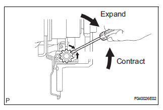
(a) Temporarily install the hub nuts.
(b) Remove the hole plug, and turn the adjuster and expand the shoes until the disc locks.
(c) Contract the shoe adjuster until the disc can rotate smoothly.
Standard: Return 8 notches
(d) Check that the brake disc rotates smoothly.
(e) Install the hole plug.
10. CONNECT REAR DISC BRAKE CALIPER ASSEMBLY LH
11. INSTALL REAR WHEEL Torque: 103 N*m (1,050 kgf*cm, 76 ft.*lbf)
12. INSPECT PARKING BRAKE PEDAL TRAVEL (See page PB-1)
13. ADJUST PARKING BRAKE PEDAL TRAVEL (See page PB-1)
 Inspection
1. INSPECT BRAKE DISC INSIDE DIAMETER
(a) Using a brake drum gauge or equivalent, measure
the inside diameter of the disc.
Standard inside diameter:
190 mm (7.480 in.)
Maximum inside diameter ...
Other materials:
Short to GND in CAN Bus Line
DESCRIPTION
A short to GND is suspected in the CAN bus wire when the resistance between
terminals 4 (CG) and 6
(CANH), or terminals 4 (CG) and 14 (CANL) of the DLC3 is below 200 Ω.
Symptoms
Trouble Area
The resistance between terminals 6 (CANH) and 4 (CG), or ter ...
Power slide door warning buzzer
INSPECTION
1. INSPECT POWER SLIDE DOOR WARNING BUZZER LH
Check the resistance of the buzzer.
Resistance
If the result is not as specified, replace the buzzer.
NOTICE:
The circuit that causes the buzzer to sound is
built into the slide door ECU, not around the
buzzer.
Direct ...
Open in Stop Light Switch Circuit
DTC C1249/49 Open in Stop Light Switch Circuit
DESCRIPTION
This skid control ECU inputs the stop light switch signal and detects the
status of brake operation.
The skid control ECU has an open detection circuit. If an open in the stop light
switch input line or GND
side stop light circuit ...
