Toyota Sienna Service Manual: Removal
1. DISCHARGE FUEL SYSTEM PRESSURE HINT: See page FU-1.
2. DISCONNECT CABLE FROM NEGATIVE BATTERY TERMINAL
3. REMOVE NO. 1 ENGINE UNDER COVER
4. DRAIN ENGINE COOLANT (See page CO-6)
5. REMOVE FRONT WIPER ARM HEAD CAP (See page WW-4)
6. REMOVE FRONT WIPER ARM RH (See page WW-4)
7. REMOVE FRONT WIPER ARM LH (See page WW-4)
8. REMOVE COWL TOP VENTILATOR LOUVER SUBASSEMBLY (See page WW-4)
9. REMOVE WINDSHIELD WIPER MOTOR AND LINK ASSEMBLY (See page WW-4)
10. REMOVE NO. 1 COWL TOP TO COWL BRACE INNER
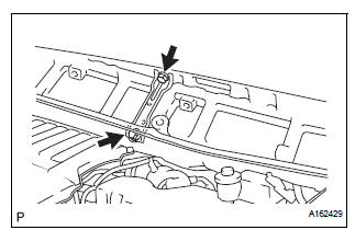
(a) Remove the 2 bolts and the No. 1 cowl top to cowl brace inner.
11. REMOVE COWL TOP PANEL SUB-ASSEMBLY OUTER FRONT
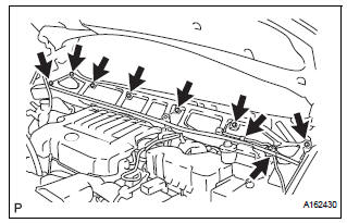
(a) Remove the wire harness clamp.
(b) Disconnect the fuel pump resistor connector.
(c) Remove the 7 bolts and the cowl top panel outer front.
12. REMOVE V-BANK COVER SUB-ASSEMBLY (See page EM-28)
13. REMOVE AIR CLEANER CAP SUB-ASSEMBLY
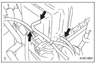
(a) Disconnect the 3 vacuum hoses.
(b) Remove the No. 2 ventilation hose and air cleaner hose band.
(c) Disconnect the vacuum hose (EVAP) from the air cleaner hose.
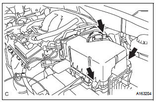
(d) Remove the 2 bolts and air cleaner cap subassembly.
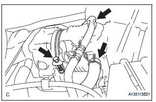
14. REMOVE INTAKE AIR SURGE TANK ASSEMBLY
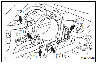
(a) Disconnect the 2 water by-pass hoses from the throttle with motor body assembly. (*1) (b) Disconnect the fuel vapor feed hose assembly.(*2) (c) Disconnect the throttle with motor body assembly connector and clamp. (*3)
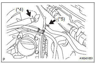
(d) Disconnect the No. 1 ventilation hose. (*4) (e) Disconnect the union to check valve hose. (*5)
(f) Disconnect the connector.
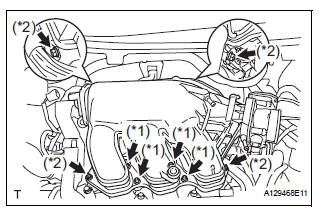
(g) Using a 5 mm socket hexagon wrench, remove the 4 bolts. (*1) (h) Remove the 2 nuts, 2 bolts, and intake air surge tank. (*2) (i) Remove the gasket from the intake air surge tank.
15. DISCONNECT FUEL TUBE SUB-ASSEMBLY
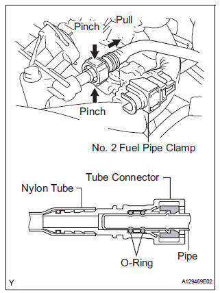
(a) Remove the No. 2 fuel pipe clamp.
(b) Pinch the tube connector and pull out the fuel pipe.
NOTICE:
|
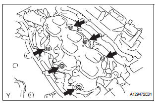
16. REMOVE FUEL INJECTOR ASSEMBLY
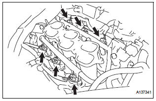
(a) Disconnect the 6 fuel injector connectors.
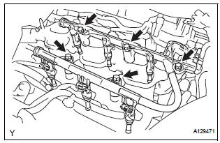
(b) Remove the 5 bolts and fuel delivery pipe subassembly together with the 6 fuel injectors.
| NOTICE: Be careful not to drop the fuel injectors when removing the fuel delivery pipe sub-assembly. |
(c) Remove the 6 injector vibration insulators from the intake manifold.
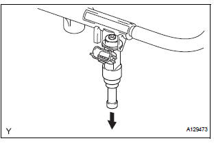
(d) Pull out the fuel injectors from the fuel delivery pipe sub-assembly
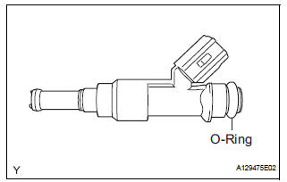
(e) Remove the 6 O-rings from the fuel injectors.
 Components
...
 Inspection
1. INSPECT FUEL INJECTOR ASSEMBLYV
(A) inspect the injector resistance.
(1) Using an ohmmeter, measure the resistance
between the terminals.
Standard resistance
If the resistance is not a ...
Other materials:
Removal
1. PRECAUTION
CAUTION:
Be sure to read "PRECAUTION" thoroughly before
servicing.
2. DISCONNECT CABLE FROM NEGATIVE BATTERY
TERMINAL
CAUTION:
Wait for 90 seconds after disconnecting the cable to
prevent the airbag working.
3. REMOVE FRONT SEAT ASSEMBLY (for Manual Seat)
4. REMOVE ...
Removal
1. REMOVE FRONT SEAT INNER BELT ASSEMBLY
HINT:
Refer to the instructions for disassembly of the front seat assembly
(for flat type).
Refer to the instructions for disassembly of the front seat assembly
(for manual seat).
Refer to the instructions for disassembly of the fro ...
TC and CG Terminal Circuit
DESCRIPTION
DTC output mode is set by connecting terminals TC and CG of the DLC3.
The DTCs are displayed by the blinking pattern of the ABS warning light.
WIRING DIAGRAM
HINT:
When warning lights continue to blink, a ground short in the wiring of terminal
TC of the DLC3 or an
internal ...
