Toyota Sienna Service Manual: SRS Warning Light does not Come ON
DESCRIPTION
WIRING DIAGRAM
INSPECTION PROCEDURE
1 CHECK BATTERY
- Measure the voltage of the battery.
Standard voltage: 11 to 14 V
 CHECK AND REPLACE BATTERY OR
CHARGING SYSTEM
CHECK AND REPLACE BATTERY OR
CHARGING SYSTEM

2 CHECK CONNECTORS
- Turn the ignition switch to the LOCK position.
- Disconnect the negative (-) terminal cable from the battery, and wait for at least 90 seconds.
- Check that the connectors are properly connected to the center airbag sensor assembly and the combination meter assembly.
OK: The connectors are properly connected.
 CONNECT CONNECTORS

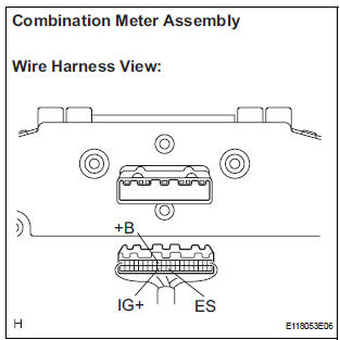
3 CHECK WIRE HARNESS (SOURCE VOLTAGE OF COMBINATION METER ASSEMBLY)
- Turn the ignition switch to the LOCK position.
- Disconnect the negative (-) terminal cable from the battery, and wait for at least 90 seconds.
- Disconnect the connector from the combination meter assembly.
- Connect the negative (-) terminal cable to the battery, and wait for at least 2 seconds.
- Turn the ignition switch to the ON position.
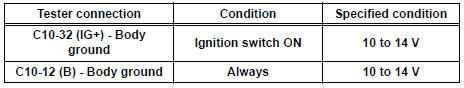
- Measure the voltage according to the value(s) in the table below.
Standard voltage
- Turn the ignition switch to the LOCK position.
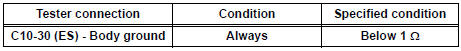
- Measure the resistance according to the value(s) in the table below.
Standard Resistance
 REPAIR OR REPLACE WIRE
HARNESS
REPAIR OR REPLACE WIRE
HARNESS

4 CHECK SRS WARNING LIGHT
- Turn the ignition switch to the LOCK position.
- Disconnect the negative (-) terminal cable from the battery, and wait for at least 90 seconds.
- Connect the connector to the combination meter assembly.
- Disconnect the connector from the center airbag sensor assembly.
- Connect the negative (-) terminal cable to the battery, and wait for at least 2 seconds.
- Turn the ignition switch to the ON position.
- Check the SRS warning light condition.
OK: After the primary check period, SRS warning light goes off for approximately 10 seconds, and remains on. HINT: The primary check period is approximately 6 seconds after the ignition switch is turned to the ON position.
 REPLACE COMBINATION METER
ASSEMBLY
REPLACE COMBINATION METER
ASSEMBLY

REPLACE CENTER AIRBAG SENSOR ASSEMBLY
 SRS Warning Light Remains ON
DESCRIPTION
The SRS warning light is located on the combination meter assembly.
When the SRS is normal, the SRS warning light comes on for approximately 6
seconds after the ignition
switch is t ...
 Diagnosis Circuit
DESCRIPTION
DTC output mode is set by connecting terminals TC and CG of the DLC3.
DTCs are displayed by blinking the SRS warning light.
HINT:
When each warning light stays blinking, a g ...
Other materials:
Releasing and stowing the seat belt (for the third center seat)
To release plate “B”, press the
release button on buckle “B”.
To release plate “A”, insert the
key or plate “B” into
the hole on buckle “A”.
Retract the belt slowly when
releasing and stowing the seat
belt.
Insert the seat belt plates into
...
Removal
1. DISCONNECT CABLE FROM NEGATIVE BATTERY
TERMINAL
2. REMOVE REAR NO. 2 SEAT LEG SIDE GARNISH SUB-ASSEMBLY
Disengage the 9 clips and remove the rear No. 2
seat leg side garnish sub-assembly.
Remove the 9 clips from the rear No. 2 seat leg side
garnish sub-assembly.
3. ...
Short in Curtain Shield Squib RH Circuit
DTC B1160/83 Short in Curtain Shield Squib RH Circuit
DESCRIPTION
The curtain shield squib RH circuit consists of the center airbag sensor
assembly and the curtain shield
airbag assembly RH.
The circuit instructs the SRS to deploy when deployment conditions are met.
DTC B1160/83 is record ...
